Heat exchanger with flat tubes

a technology of heat exchanger and flat tube, which is applied in the direction of light and heating apparatus, machines/engines, laminated elements, etc., can solve the problem of insufficient resistance to enormous alternating temperature loads

Active Publication Date: 2005-07-28
MODINE MFG CO
View PDF66 Cites 101 Cited by
  • Summary
  • Abstract
  • Description
  • Claims
  • Application Information

AI Technical Summary

Benefits of technology

[0015] According to another form of this aspect of the invention, matching tube pieces are inserted into the ends of the heat exchanger tubes to reinforce the heat exchanger tubes. In a further form, the tube pieces have inserts with connectors running generally in the stacking direction, where the connectors have a contour permitting length changes in the stacking direction of the heat exchanger tubes.
[0016] According to still another form of this aspect of the invention, the collecting tank has a first selected one of an input and an output for communication of the first medium with the tubes, and is connected to a section of the tube stack bounded by two connection planes and communicating with flow paths defined between the tubes. The collecting tank also has a second selected one of an output and an input for communication of a second medium wit...

Problems solved by technology

Heat exchangers incorporated, for example, in an exhaust gas recirculation system of a vehicle as an exhaust heat exchanger, may be inadequate to withstand the enormous alternating temperature loads, a problems which has been gener...

Method used


Image

  • Heat exchanger with flat tubes
  • Heat exchanger with flat tubes
  • Heat exchanger with flat tubes

Examples


Embodiment Construction

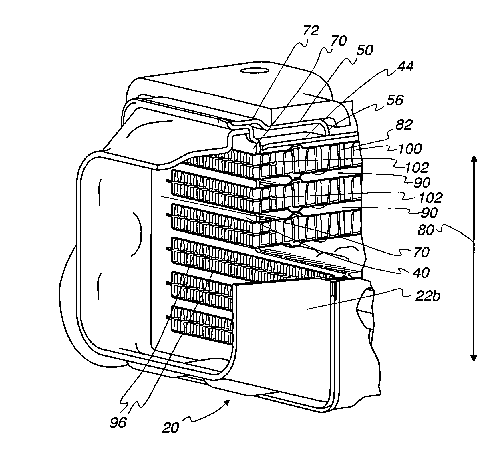
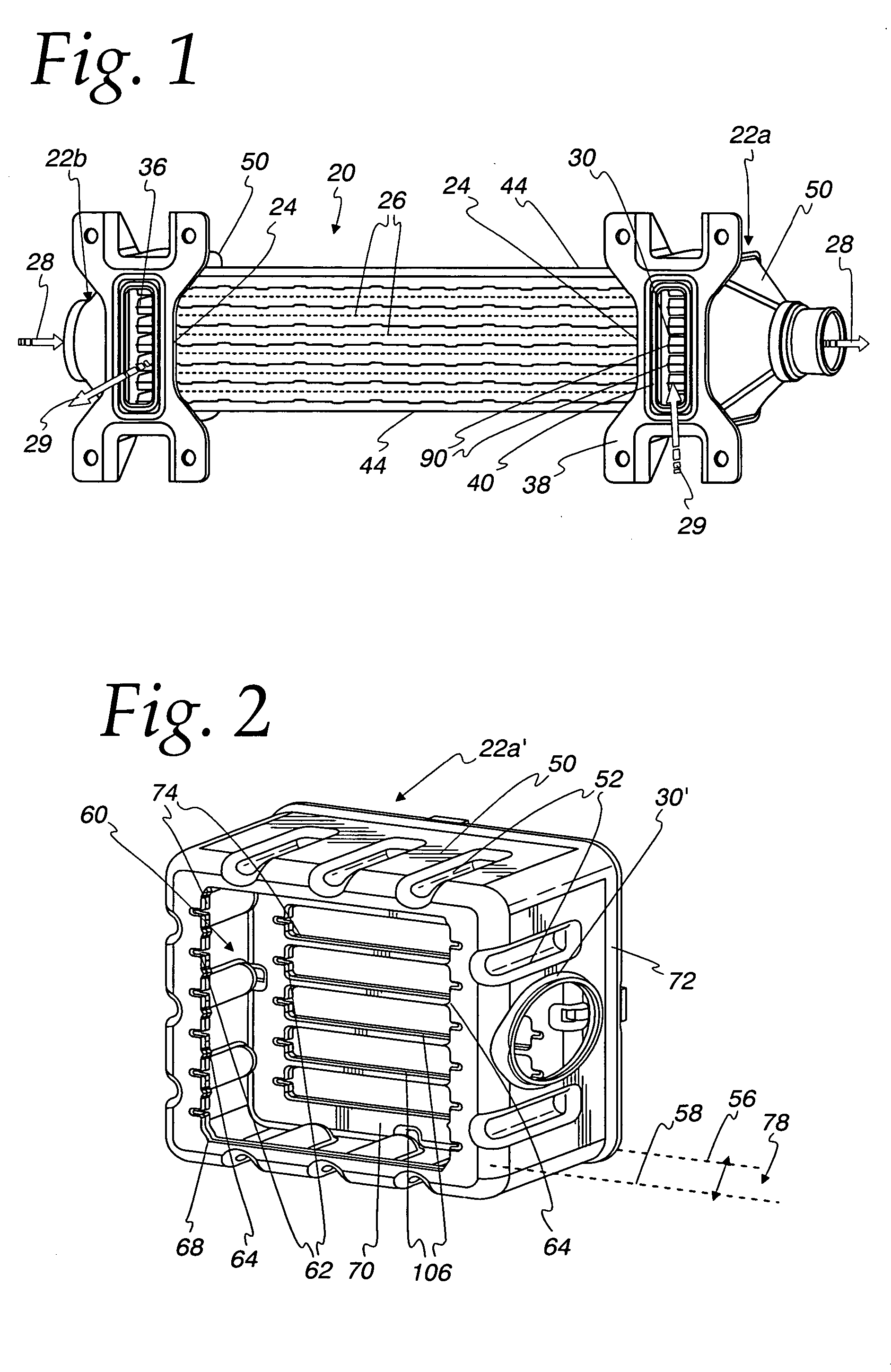
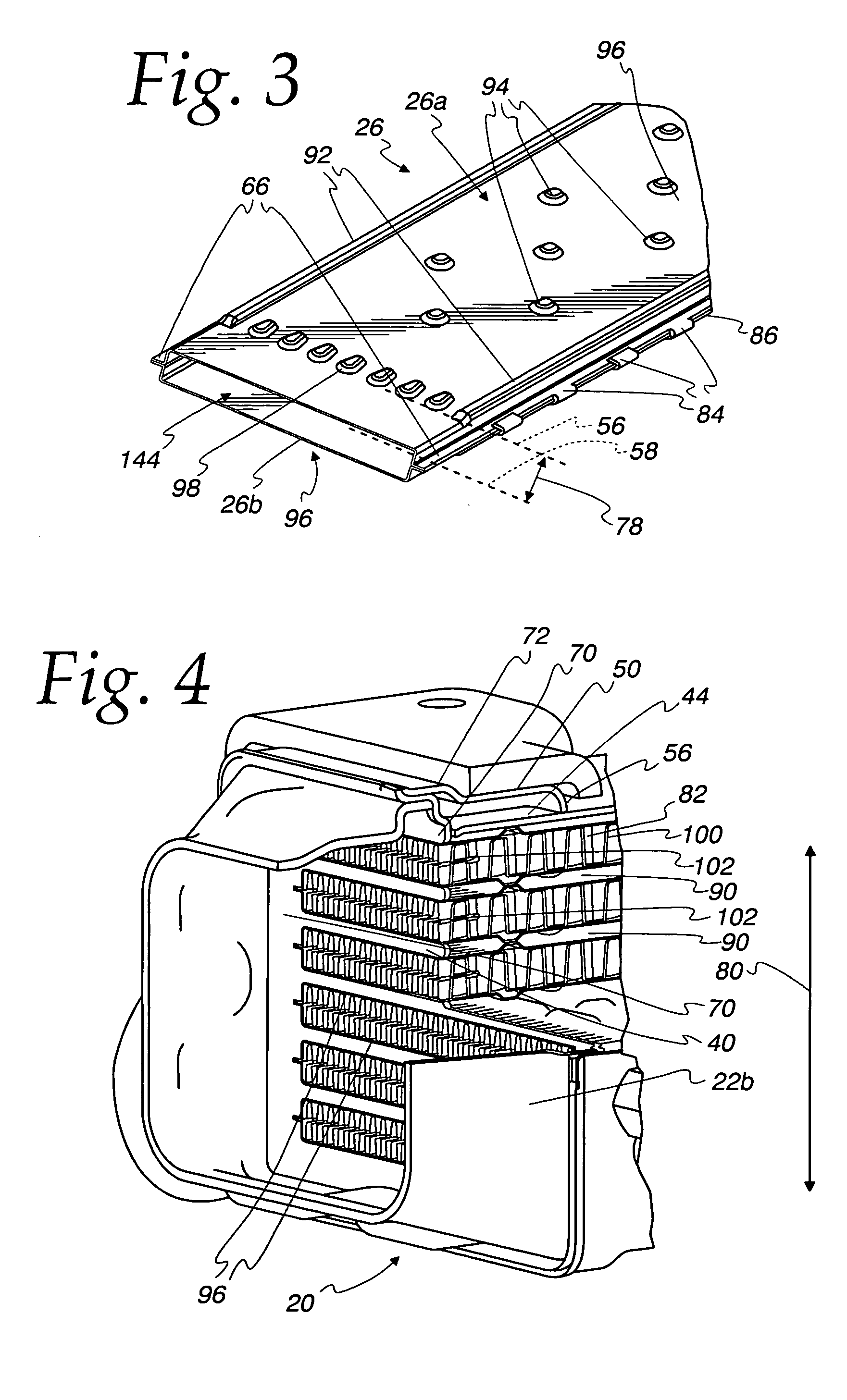
[0037] The practical examples in FIGS. 1-12 are exhaust gas heat exchangers 20 which may be incorporated in a manner (not shown) in the exhaust gas recirculation system of a vehicle and utilize the coolant of the vehicle engine as cooling medium. However, it should be appreciated that the heat exchanger can be used with equal advantages as a charge air cooler cooled with coolant or for other purposes, especially where high alternating temperature loads occur.

[0038] In the illustrated practical examples, one collecting tank 22 is provided on each end 24 of a stack of heat exchanger tubes 26. Consequently, the exhaust (arrow 28) in the heat exchanger 20 depicted in FIG. 1 flows in at the left collecting tank 22b, is distributed to and flows through the heat exchanger tubes 26, and then leaves the heat exchanger 20 via the other collecting tank 22a on the right. The cooling liquid (dashed arrow 29) enters the inlet 30 of the right collecting tank 22a, is distributed to and flows throu...


PUM


Abstract

A heat exchanger with a plurality of stacked flat tubes and a collecting tank having a wall extending around the entire periphery of, and connected to, the end of the stacked flat tubes. A first medium may be distributed through the collecting tank and flat tubes. Internal inserts are in the flat tubes, with the inserts being bonded between the broad sides of the tubes and, in the region of connection of the tubes to the collecting tank, being configured to compensate for length changes in the stacking direction caused by temperature changes, as by recesses in connectors such as wave flanks or by corrugated wave flanks. The flat tubes with inserts such as described may be separately provided for use in manufacture of heat exchangers.

Description

CROSS REFERENCE TO RELATED APPLICATION(S) [0001] Not applicable. FEDERALLY SPONSORED RESEARCH OR DEVELOPMENT [0002] Not applicable. REFERENCE TO A MICROFICHE APPENDIX [0003] Not applicable. TECHNICAL FIELD [0004] The present invention is directed toward heat exchangers, and particularly toward heat exchangers with flat tubes adapted to accommodate alternating temperature heat loads. BACKGROUND OF THE INVENTION AND TECHNICAL PROBLEMS POSED BY THE PRIOR ART [0005] Heat exchangers are known in which an inlet collecting tank distributes one medium in flat heat exchanger tubes and an outlet collecting tank receives the one medium from the flat heat exchanger tubes and convey it further. The collecting tank has a wall that extends around the entire periphery of the end of a stack of heat exchanger tubes and over a certain length section of the heat exchanger tubes, the wall having at least one inlet and / or an outlet for the other medium that flows between the heat exchanger tubes. An inte...

Claims


Application Information

Patent Timeline
IPC IPC(8): F02B29/04F02M25/07F28D7/16F28D9/00F28F3/02F28F3/04F28F9/02
CPCF02B29/0462F02M25/0714F02M25/0737F28D7/1684F28D9/0031F28D21/0003F28F2225/00F28F3/044F28F9/0219F28F2235/00Y02T10/121Y02T10/146F28F2265/26F28F3/025F02M26/11F02M26/32F28F2225/06F28F2225/04F28F9/185F28F1/025F28F2225/08Y02T10/12
Inventor AMBROS, PETERSOLDNER, JORGSTRAHLE, ROLANDSTOLZ, ANDREASMERZ, DIETERNIES, JENSTHUMM, SVENMULLER, KATJASCHATZ, HARALDKOTTAL, PETER C.GRIPPE, FRANK M.
Owner MODINE MFG CO
Why Eureka
Try Eureka