Primary conductor arrangement for a system for the inductive transmission of electrical energy

a technology of inductive transmission and primary conductor, which is applied in the direction of power current collectors, electric vehicles, domestic applications, etc., can solve the problem of insufficient energy density of the magnetic field generated by the primary circuit and can only be achieved along the conductor arrangement, and achieve high magnetic field density

Inactive Publication Date: 2005-07-28
WAMPFLER
View PDF2 Cites 13 Cited by
  • Summary
  • Abstract
  • Description
  • Claims
  • Application Information

AI Technical Summary

Benefits of technology

[0010] The invention proposes to divide the conductor arrangement into a plurality of adjacent sections, wherein each section comprises an outgoing line and a return line as well as connection lines that connect the outgoing line and the return line, and wherein the sections are arranged relative to one another such that two successive sections overlap in the region near their connection line. The division of the primary circuit into several sections makes it possible to achieve a sufficiently high magnetic field density along the entire conductor arrangement since a current can be separately applied to each section by a current source. The overlap of the adjacent sections at their edges ensures a homogenous field-strength distribution in this transition area. A largely homogenous transition of the magnetic field-strength distribution from one section to the adjacent section not only ensures a uniform energy supply to the movable consumer along the line segment of the primary circuit, but is also particularly required if the magnetic field of the primary circuit is simultaneously utilized for tracking the movable consumer along the line segment.

Problems solved by technology

A sufficient energy density of the magnetic field generated by the primary circuit can only be achieved along the conductor arrangement with conventional current sources if the conductor arrangements have a limited range, i.e., a limited length of the outgoing line and the return line.

Method used


Image

  • Primary conductor arrangement for a system for the inductive transmission of electrical energy
  • Primary conductor arrangement for a system for the inductive transmission of electrical energy
  • Primary conductor arrangement for a system for the inductive transmission of electrical energy

Examples


Embodiment Construction

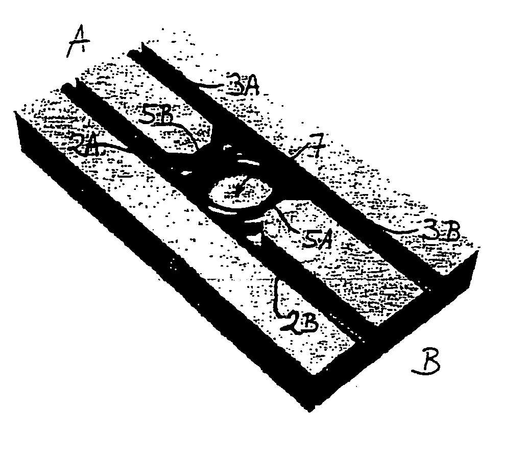
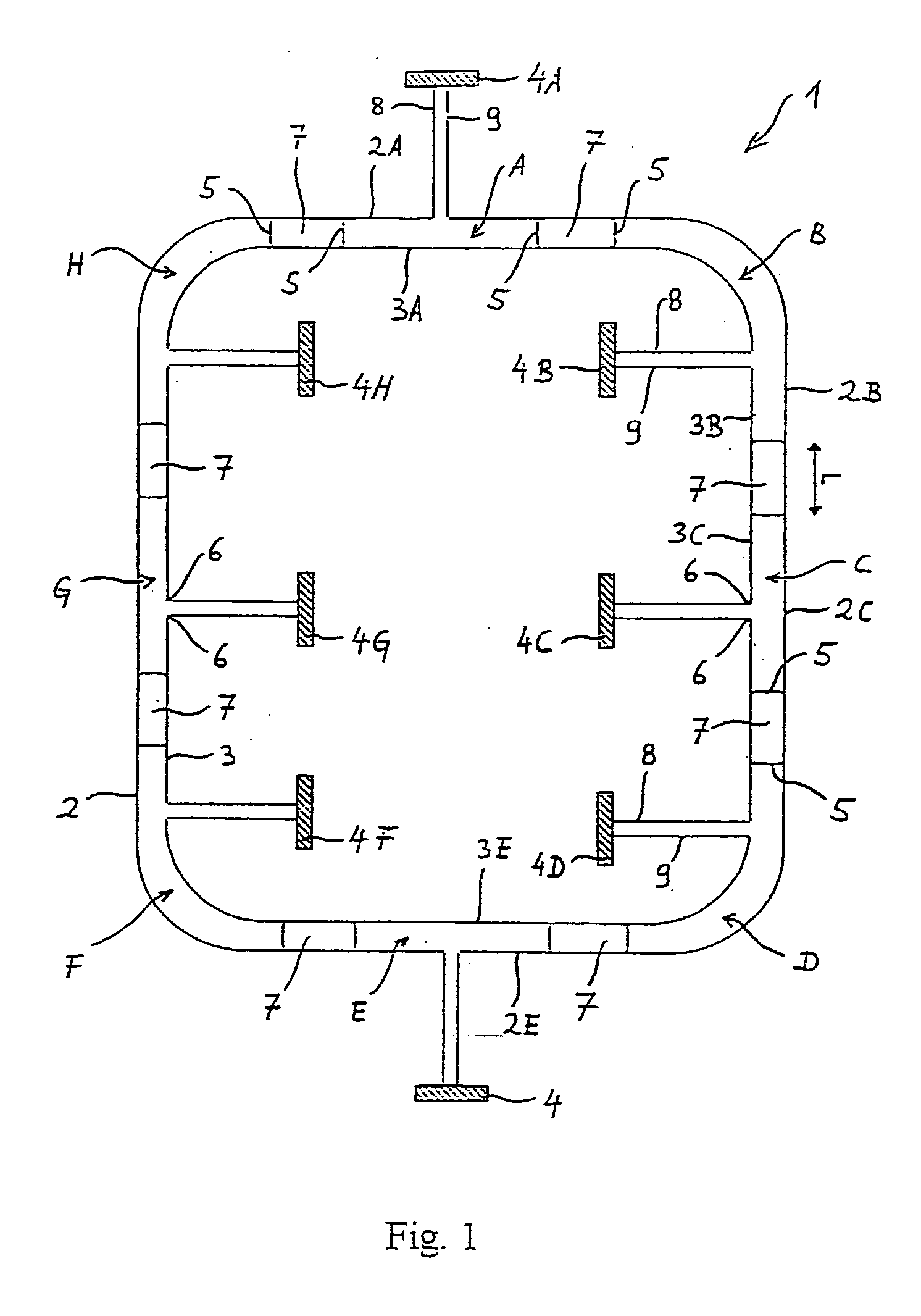
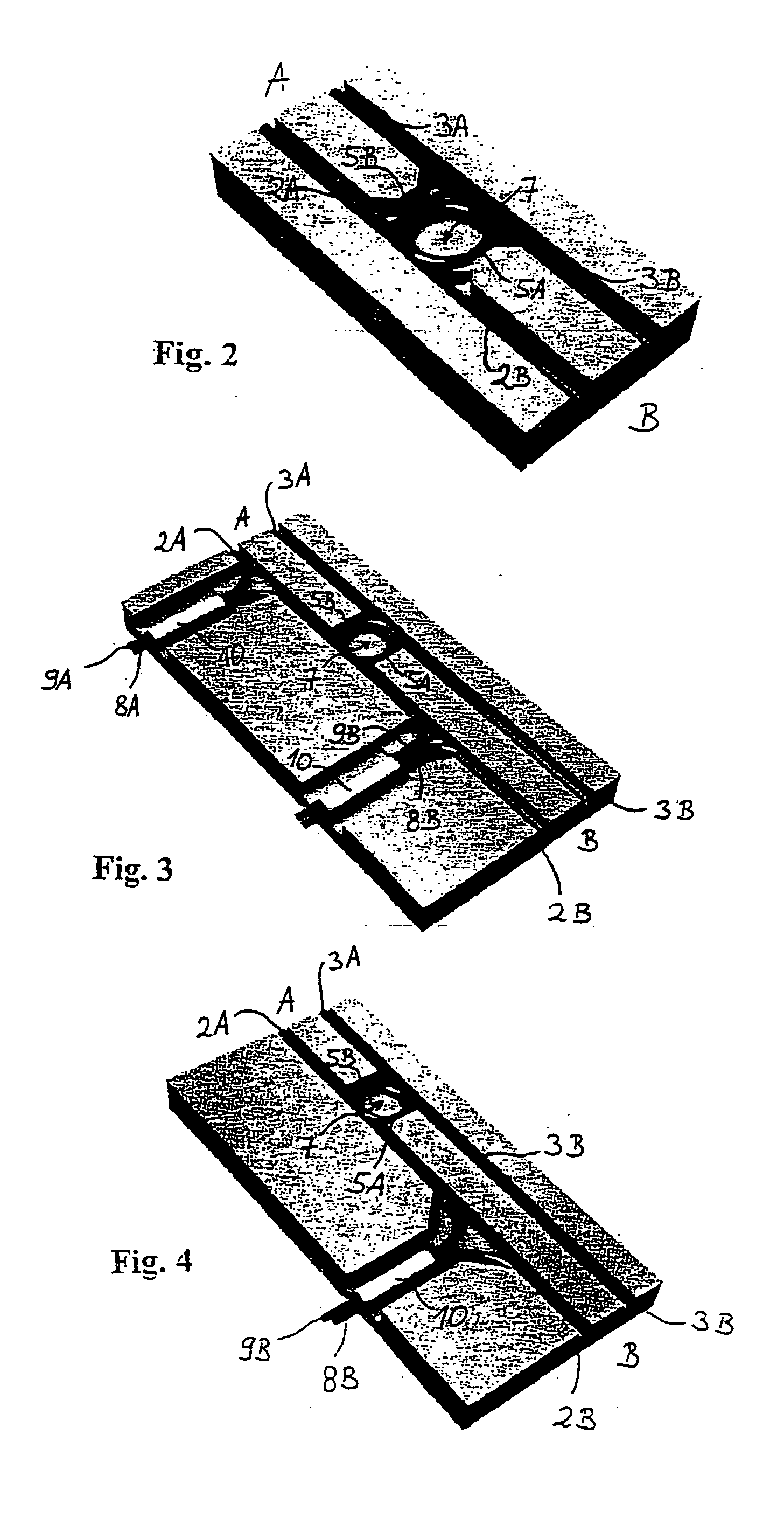
[0018] g. FIG. 1 schematically shows a primary circuit for a system for the inductive transmission of electrical energy that is formed by a primary conductor arrangement 1 according to the invention, said system being used for transmitting electrical energy to a consumer that can be displaced along the primary conductor arrangement 1. The primary conductor arrangement 1 is divided into a plurality of adjacent sections (A-H). Each of these sections (A-H) contains an outgoing line 2, a return line 3 and a connection line 5 that connects the outgoing line and the return line. The outgoing lines and the return lines of the sections (A-H) are respectively identified by the reference symbols 2X, 3X and 5X in FIG. 1, wherein X designates the respective conductor section (A-H).

[0019] The outgoing lines 2 and the return lines 3 are arranged parallel to one another in each section A-H, and the connection lines 5 form the transition between the outgoing line 2 and the return line 3. In this c...


PUM


Abstract

A primary conductor arrangement for a system for the inductive transmission of electrical energy, wherein the conductor arrangement includes an outgoing line and a return line that extend parallel to one another and can be connected to a current source in order to apply an electric current to the outgoing line and the return line. The conductor arrangement is divided into a plurality of adjacent sections, wherein each section contains an outgoing line and a return line as well as connection lines that connect the outgoing line and the return line. The sections are arranged relative to one another such that two adjacent sections overlap in a region near their connection line.

Description

RELATED APPLICATION [0001] This application is a continuation of International Patent Application No. PCT / EP03 / 01777, filed Feb. 21, 2003, the contents of which are here incorporated by reference in their entirety. Applicant claims the benefit of 35 USC Section 120.BACKGROUND OF THE INVENTION [0002] 1. Field of the Invention [0003] The invention pertains to a primary conductor arrangement for a system for the inductive transmission of electrical energy. [0004] 2. Prior Art [0005] Conductor arrangements for the contactless, inductive transmission of energy, in which a primary circuit is formed by two parallel lines that are spaced apart from one another by a certain distance, are generally known from the prior art, for example, according to DE 197 46 919 A1. A movable consumer that contains a secondary circuit, for example, a ground transport vehicle, can be displaced along such a primary conductor arrangement, wherein the aforementioned secondary circuit serves for the inductive rec...

Claims


Application Information

Patent Timeline
Patent Type & Authority Applications(United States)
IPC IPC(8): A47B85/08B60L5/00
CPCB60L5/005
Inventor GREEN, ANDREW
Owner WAMPFLER
Why Eureka
Try Eureka