
a wind generator

A technology for wind power generators and power generation modules, which is applied in the direction of electrical components, electromechanical devices, etc., can solve the problems of high temperature of generators and affect the use of generators, and achieve the effect of high magnetic field density, high uniformity, and low start-up wind force

Inactive Publication Date: 2017-02-08
王秋安
View PDF6 Cites 0 Cited by
  • Summary
  • Abstract
  • Description
  • Claims
  • Application Information

AI Technical Summary

Problems solved by technology

And the main heat is generated by the first two, which directly leads to high temperature inside the generator, which affects the use

Method used


Image

  • a wind generator
  • a wind generator
  • a wind generator

Examples


Embodiment 1

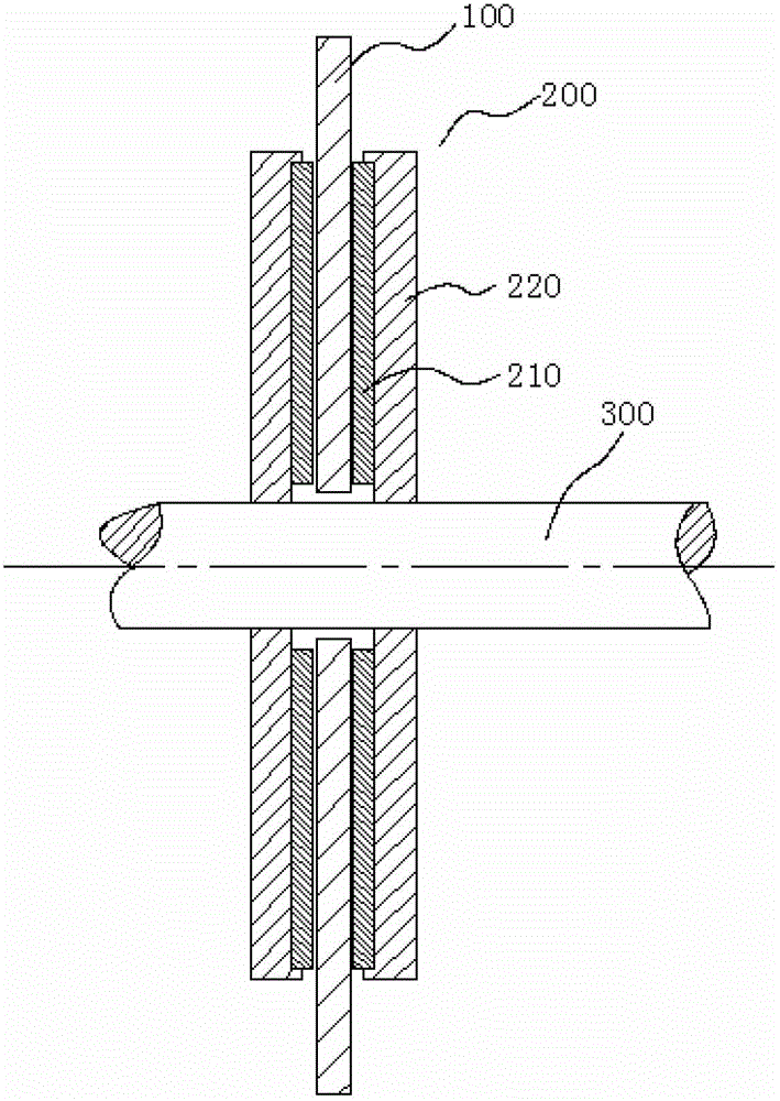
[0028] see figure 1 , a wind power generator, including a coil assembly 100, a magnetic steel assembly 200, a rotating shaft 300 and an impeller (not shown in the figure), and both sides of the coil assembly 100 are provided with a magnetic steel assembly 200.

[0029] see Figure 4 , the coil assembly 100 is disc-shaped, and the disc-shaped coil assembly 100 is provided with a wire 110 for cutting magnetic lines of force. In one preferred embodiment of the present invention, the coil assembly 100 is a PCB, and the two sides of the PCB are both A circuit is etched, and for a general generator, the coil assembly 100 can be an ordinary electromagnetic wire circuit.

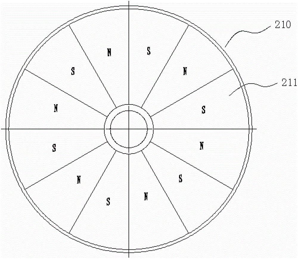
[0030] see figure 1 and image 3 The magnetic steel assembly 200 includes a magnetic steel 210 and a magnetic yoke 220. Both the magnetic steel 210 and the magnetic yoke 220 are disc-shaped. The magnetic steel 210 can be a piece of magnetic steel with multi-pole magnetization, or several pieces of magnetic steel ...

Embodiment 2

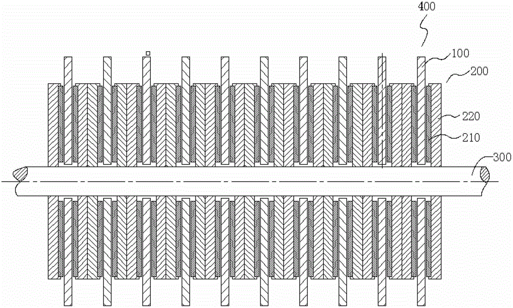
[0038] see figure 1 , a wind generator, including a coil assembly 100, a magnetic steel assembly 200, a rotating shaft 300 and an impeller (not shown in the figure), and both sides of the coil assembly 100 are provided with a magnetic steel assembly 200. And in this embodiment, the wind power generator includes more than two coil assemblies 100, the number of magnetic steel assemblies 200 is twice that of the coil assemblies 100, one coil assembly 100 and the magnetic steel assemblies 200 on both sides constitute a power generation module 400 , the power generation module 400 and the power generation module 400 are connected to each other.

[0039] see Figure 4 , the coil assembly 100 is disc-shaped, and a circuit 110 for cutting magnetic lines of force is provided on the disc-shaped coil assembly 100. In one of the preferred embodiments of the present invention, the coil assembly 100 is a PCB board, and both sides of the PCB board are The circuit is etched, and for a typical...


PUM


Abstract

The invention relates to a wind power generator, which comprises a coil assembly, magnetic steel assemblies, a rotating shaft and an impeller, wherein the magnetic steel assemblies are arranged at two sides of the coil assembly; the coil assembly is shaped as a disc, and the disc-shaped coil assembly is provided with a circuit for cutting magnetic induction lines; each magnetic steel assembly comprises magnetic steel and a magnetic yoke which are respectively shaped as a disc, a plurality of magnetic poles are uniformly arranged on each magnetic steel at intervals, each magnetic steel is arranged at one side of each magnetic yoke, one surface, where each magnetic steel is arranged, on each magnetic yoke, faces to the coil assembly; the rotating shaft passes through the coil assembly and the circle centers of the magnetic steel assemblies at two sides of the coil assembly, and the circle center of the magnetic yoke of each magnetic steel assembly is connected with the rotating shaft; and the impeller is connected to the rotating shaft. The wind power generator disclosed by invention has the advantages of high magnetic field density, high uniformity, capability of realizing multigroup input and free combination of coils, high wind power utilization rate and low start wind power.

Description

technical field [0001] The invention relates to a wind-driven generator, specifically a wind-driven generator with small start-up force, wide adaptable speed (wind force) range, high energy utilization rate, light structure, low cost and low calorific value. Background technique [0002] Wind energy is a renewable new energy source with the advantages of no pollution and environmental protection. In this era of advocating energy conservation and environmental protection, how to utilize wind energy has become a very important research topic. In the prior art, wind power generators have been widely used, but there are still many defects in the current wind power generators, for example: the starting torque of the wind power generator is relatively large, and when the wind force is small, the impeller of the wind power generator When the wind is strong, in order to prevent the rotor from running too fast, the angle of the fan blades has to be changed to reduce the utilization ...

Claims


Application Information

Patent Timeline
Patent Type & Authority Patents(China)
IPC IPC(8): H02K16/00
Inventor 王秋安
Owner 王秋安
Learn More