Stand for supporting a display in multiple orientations and a display used in combination with said stand

a technology for supporting a display and a stand, which is applied in the direction of machine supports, instruments, and electrical apparatus casings/cabinets/drawers, etc., which can solve the problems of not being able to rotate the screen and the housing, being difficult to support on one's lap, and not being able to remove the device. the effect of quick and easy removal

Inactive Publication Date: 2005-07-28
WACOM CO LTD
View PDF12 Cites 27 Cited by
  • Summary
  • Abstract
  • Description
  • Claims
  • Application Information

AI Technical Summary

Benefits of technology

[0006] These difficulties are addressed by the present invention which comprises a stand for supporting a display or PED at various angles of inclination with respect to a horizontal support surface, including a first range of small angles so that the PED can be used primarily as a tablet and a second range of larger angles so that the PED can serve primarily as a display. Moreover, the stand supports the PED so that it can be rotated 180 degrees or more in either direction from a starting point and so that it can be removed quickly and easily when a user wishes to use the PED or other display apart from the stand.
[0007] In a preferred embodiment, the invention comprises a display with a housing having a display screen, a boss extending from the side of the housing opposite the display screen, and a stand having a plate with a curved channel for receiving the boss and rotatably and removably supporting the display. The boss is provided with a flange on its free end, which flange is spaced away from the display housing by a distance greater than the width of the channel so that the flange prevents the boss from being pulled through the channel when the display is mounted in the stand. The plate is supported by two legs, one of which may be formed integrally with the plate, and the legs are hingedly connected by a lockable hinge. Each leg terminates in a pair of feet which support the stand and the display on a support surface. Handles or levers extend from either side of the stand to actuate the locking mechanisms of the locking hinge, which mechanisms preferably includes two oppositely mounted spring clutches. One of the levers releases the first spring clutch to allow the angle between the legs to be increased while the other releases a second spring clutch to allow the angle between the legs to be decreased. Balance springs are also provided to support the weight of the display and stand together and to prevent the stand from falling into its fully open position each time the first lever is actuated. Using these handles, the angle between the legs can be adjusted from between about 130 and 180 degrees, preferably about 140 degrees, which angle allows the display to lie flat or nearly flat on a support surface to between about 20 and 60 degrees, preferably about 45 degrees, in which configuration the stand can be used to support the device for use as a display. The boss on the display housing rests securely in the channel in the stand and the flange prevents the display from being removed from the channel in a direction normal to the screen on the display.
[0008] The boss is generally round, but may have one pair of parallel side edges connected by curved end sections as will be explained in more detail, and the channel preferably comprises an arc of more than 180 degrees with two ends separated by a first distance less than the long dimension of the boss and shorter than the distance between the two flat sides of the boss. This arrangement allows the boss to be placed in the stand in one orientation only; when the boss is rotated from this position, the long dimension of the boss cannot be removed through the channel and the display is locked in the stand. However, the display can be lifted out of the channel with little effort when it is returned to its initial orientation when one desires to use the display without the stand. Alternately, a plain circular boss could be used, but such a boss would not lock in the channel as described above. As the boss projects only a small distance from the rear of the display housing, it will not interfere with the use of the display in a user's lap.

Problems solved by technology

However, the leg is not removable, making the device difficult to support on one's lap, and does not permit the screen and housing to be rotated.
Stands are known that allow a flat panel display to be rotated or tilted, but these stands usually support displays at some distance above a surface so that they can be viewed as a monitor and cannot readily be disconnected from a display to allow the display to be used apart from the stand.
And, while such supports are generally adequate for supporting a flat screen in a generally vertical display orientation or in a relatively horizontal drawing mode, they do not allow a display to be removed for lap use.

Method used


Image

  • Stand for supporting a display in multiple orientations and a display used in combination with said stand
  • Stand for supporting a display in multiple orientations and a display used in combination with said stand
  • Stand for supporting a display in multiple orientations and a display used in combination with said stand

Examples


fourth embodiment

[0073] the invention is shown in FIGS. 22-25 wherein a display 400 including a housing 402 having a rear surface 404 is provided with a rotatable bearing 406 on rear surface 404. Bearing 406 is centrally located on housing rear and includes a central opening 408 to accommodate a cable 410 emerging from the display so that bearing 406 can rotate around the cable without twisting or damaging the cable. Bearing 406 further includes two openings 412 which each of which preferably includes a pair of converging wall portions 414 meeting at a vertex 415. As best seen in FIG. 24, openings 412 each open into an interior chamber 416 that is wider than opening 412 thus forming a lip or flange 418 around each opening.

first embodiment

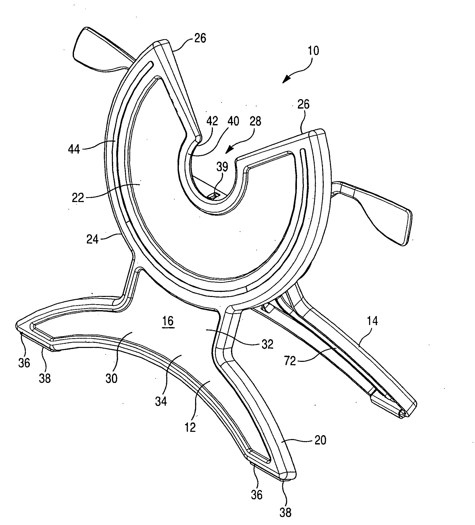
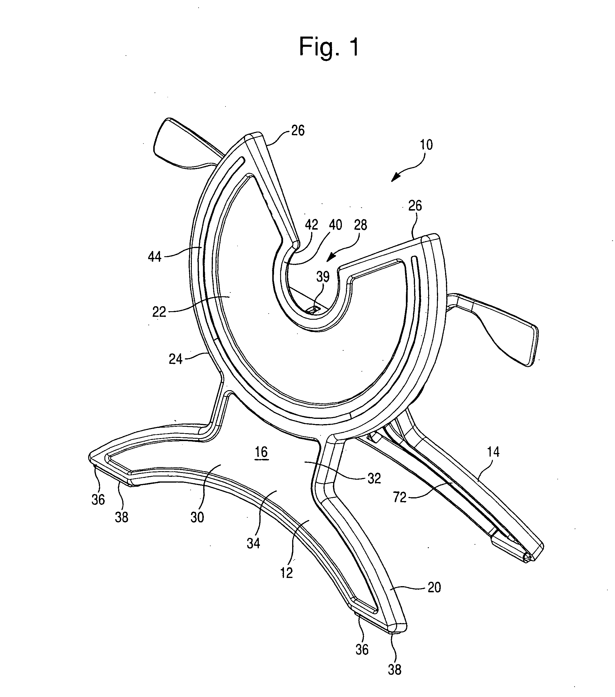
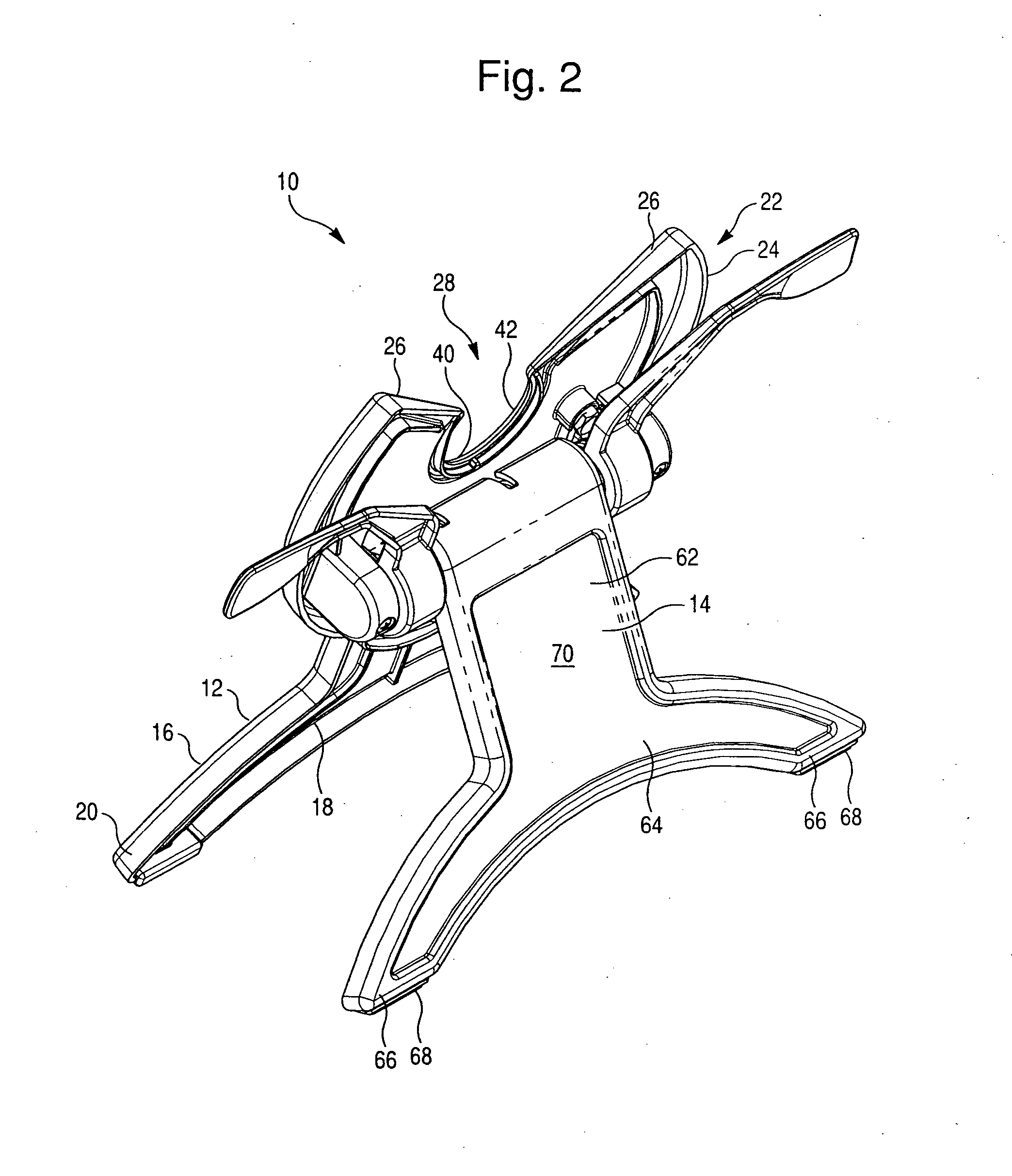
[0074] Display 400 is used with a stand 420 comprising a planar front side 422 having a V-shaped notch 424 and first and second projections 426 located one on either side of notch 424. Each projection includes a rod portion 428 and an end flange 430, and these projections are securely fastened to or integrally formed with the stand. The planar front side can be supported in any manner, for example, using a fixed leg or using the adjustable legs described above in the

[0075] In use, the display is mounted on the stand by aligning openings 412 with projections 426 and inserting projections 426 into openings 412. The openings are larger than end flanges 430 so small errors in alignment are tolerated. Converging wall portions 414 direct the projections toward vertex 415 where they are securely supported. Flanges 430 on the projections are received in chamber 416 behind lip 418 of the display and preventing the projections from being pulled out of the openings in a direction normal to the...


PUM


Abstract

An adjustable stand for rotatably and releaseably supporting a flat panel display is disclosed together with a display device usable with the stand. The display includes a boss projecting from a rear surface thereof, which boss is received in an arc-shaped channel in a plate portion of the stand. The stand further includes two hingedly connected legs and selective locking devices for controlling the angle between the legs, thereby allowing the stand hold the display in a variety of orientations with respect to a horizontal support surface.

Description

FIELD OF THE INVENTION [0001] The present invention is directed toward a stand for supporting a display and a display used in combination with the stand, and more specifically, to a pen-enabled computer display (“PED”) having a screen and a stand for mounting the PED in a first orientation for using the PED primarily as a display and in a second orientation for using the PED primarily as a tablet, in a manner that also allows the PED to be removed from the stand for lap-top use. BACKGROUND OF THE INVENTION [0002] Flat panel displays, which may comprise, for example, liquid crystal displays (“LCD's”), are becoming increasingly common and are often used as monitors for personal computers, replacing the bulky cathode ray tube (“CRT”) monitors that have heretofore been used. When used for this purpose, the displays are normally rectangular and are mounted on a user's desk in front of a keyboard with the long dimension of the rectangular panel oriented horizontally in what is commonly re...

Claims


Application Information

Patent Timeline
Patent Type & Authority Applications(United States)
IPC IPC(8): G01S19/05F16M11/06F16M11/10
CPCF16M11/02F16M11/041F16M11/06F16M11/10F16M11/105Y10S248/922F16M13/00F16M2200/024F16M2200/044F16M2200/08Y10S248/919F16M11/2021
Inventor RAWLINGS, SCOTTNISHINO, HIDEKIPOLLMANN, KONRADSAYLER, DAVID
Owner WACOM CO LTD
Why Eureka
Try Eureka