Self-propelled pool chemical dispenser

a dispenser and self-propelled technology, applied in the field of pools, can solve the problems of difficult maintenance, many unsightly chlorine and other pool chemical distribution systems, and chemical distributors thereby detracting from the decor of the pool

Inactive Publication Date: 2005-07-28
SHERR OTIS P
View PDF5 Cites 11 Cited by
  • Summary
  • Abstract
  • Description
  • Claims
  • Application Information

AI Technical Summary

Benefits of technology

[0015] The principal object of the self-propelled pool chemical dispenser is to create a means to evenly distribute and control the dispersement of chemicals in pools, ponds and waterways.
[0022] Yet another object is to create a self-propelled pool chemical dispenser that can navigate freely or be tethered on a line to an anchor and rotate within a confined circular area.
[0025] The preferred embodiment of this invention will take the shape of a fish but it must be understood that it may be created in a variety of different shapes and still fall within the scope of this patent. This device has been designed to disperse chemicals for the purpose of sanitation or purification of water in swimming poor and spas as well as in ponds and waterways. One of the unique features of this device allows it to propel itself through the water with an electric motor powered by a battery that in some cases may be recharged by photovoltaic power cells on the exterior surface. The action of propelling the device through the water by the means of moving a tail back and forth will minimize the device being tangled by weeds or other articles in the water when used in ponds and waterways.
[0026] As it propels itself through the water, water is taken in the front through a water intake orifice that in some cases will be in the configuration of the mouth of a fish and exit through water exit orifices that in some cases will be in the configuration of the gills of a fish. The water passing through the internal cavity of the head or frontal element will dissolve the water-soluble chemicals and disperse them through the water exit orifices. The amount of dissolved chemicals can be controlled by one or more sliding doors within the internal cavity of the head or frontal element. The stability of the device is maintained by the means of a flotation unit at the top of the body and ballast at the bottom. Direction of the device can be either maintained or altered by the means of dorsal and pectoral fins at the top and bottom of the device. As it floats higher in the water it displays more of the dorsal fin when the chemicals have been depleted.
[0027] The device is compact, aesthetically attractive, long lasting, easily filled with chemicals and precisely adjustable, and is effective and efficient. The self-propelled pool chemical dispenser can be used with soluble source materials of diverse manufacture, thus giving the user freedom to select the source material he deems best for his needs. The self-propelled pool chemical dispenser is especially useful with source chemicals provided in tablet or stick form.

Problems solved by technology

Many of the chlorine and other pool chemical distribution systems are unsightly when exposed in the pool area.
The chemical distributors thereby detract from the decor of the pool in addition to being difficult to maintain because of their complicated operation.
Additionally, these chemical distribution systems have been designed specifically for the use in swimming pools only and are not self-propelled or would not be usable in other environments like ponds or waterways.
This patent describes a floating chemical dispenser but does not have the capability of moving itself through the water or the ability of being used in other environments.
This patent describes another floating chemical dispenser but does not have the capability of moving itself through the water or the ability of being used in other environments.
Again this patent describes another floating chemical dispenser but does not have the capability of moving itself through the water or the ability of being used in other environments.

Method used


Image

  • Self-propelled pool chemical dispenser
  • Self-propelled pool chemical dispenser
  • Self-propelled pool chemical dispenser

Examples


Embodiment Construction

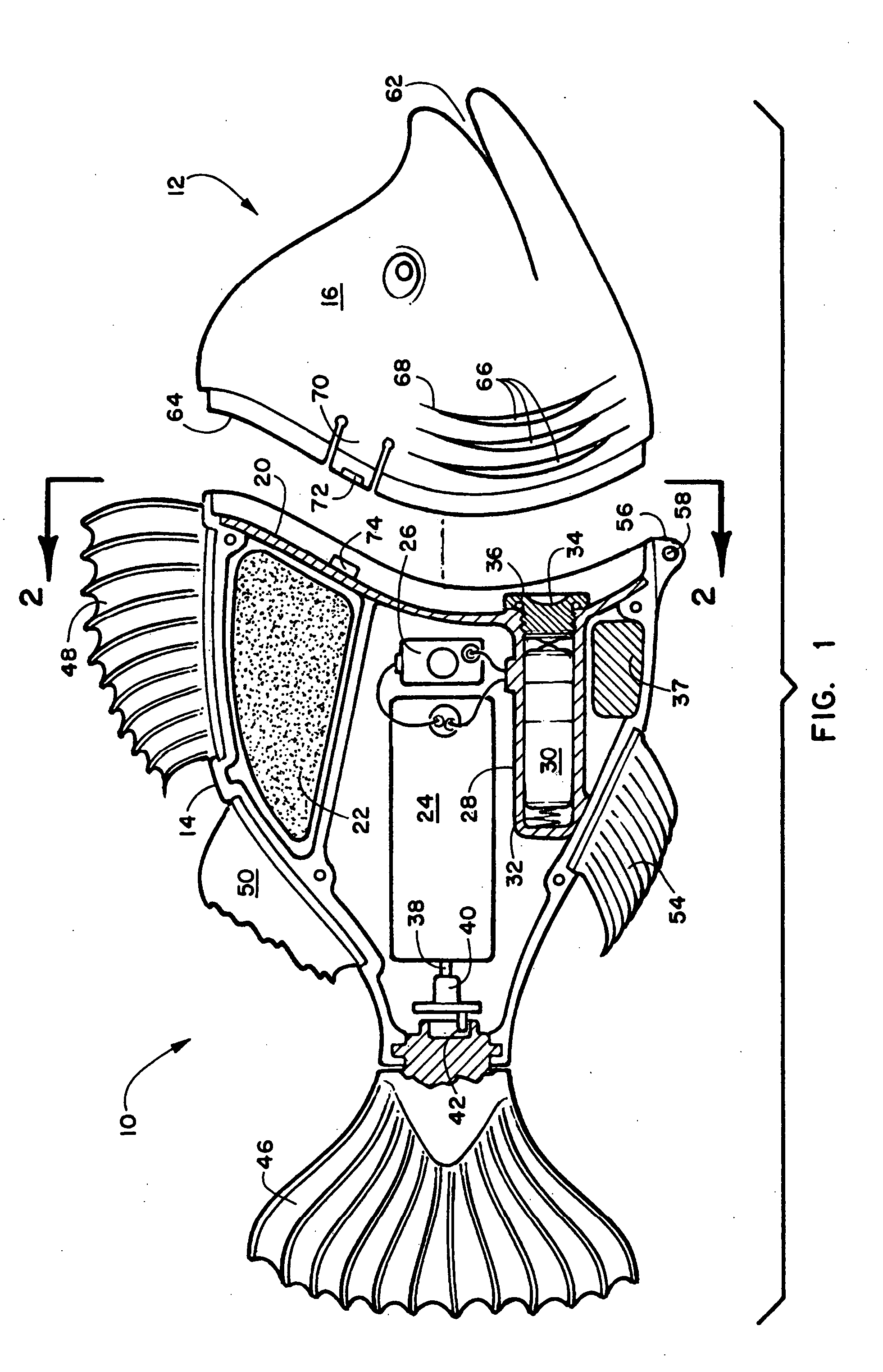
[0040] Referring now to the drawings, wherein similar parts of the self-propelled pool chemical dispenser 10 are identified by like reference numerals, there is seen in FIG. 1 a side elevation of the preferred embodiment of the self-propelled pool chemical dispenser 10 shown as a conventional freshwater fish 12. The device has been sectioned through the body 14 with the head or frontal element 16 exploded away, where the chemicals to dispense are stored. The body 14 has been shown with the left side 18 removed and the front wall 20 shown in section to display the flotation unit 22, the sealed electric motor 24 with wires going to the on / off switch 26 and the sealed battery compartment 28. The battery 30 is held in place between a spring 32 and a threaded cap 34. The battery compartment 28 is sealed by the means of an o-ring 36 under the threaded cap 34. Below the sealed battery compartment 28 is a ballast unit 37 to work in combination with the flotation unit 22 to maintain the desi...


PUM

PropertyMeasurementUnit
buoyancyaaaaaaaaaa
areaaaaaaaaaaa
chemicalaaaaaaaaaa

Abstract

The present invention is directed to a self propelled chemical dispensing apparatus. It describes an invention that will take the shape of a fish but will also be in a variety of different shapes and configurations. The device has been conceived to disperse chemicals for the purpose of sanitation or purification of water in swimming pools and spas as well as in ponds and waterways. A unique feature of this device allows it to propel itself through the water by moving a tail back and forth or by a propeller powered by an electric motor and battery. The battery in some cases may be recharged by the means of photovoltaic power cells on the exterior surface. As it propels itself through the water, water is taken in the front through a water intake orifice. The water passing through the internal cavity of the head or frontal element will dissolve the water-soluble chemicals and disperse them through the water exit orifices. The amount of dissolved chemicals can be controlled by one or more sliding doors within the internal cavity of the head or frontal element.

Description

FIELD OF THE INVENTION [0001] This invention relates to the field of pools, which require the dispersement of chemicals for the purpose of sanitation or purification. More specifically this patent deals with the even distribution and controlled dispersement of chemicals in pools, ponds and waterways. The most common usage of this invention will be in the field of dispersing chemicals evenly throughout a swimming pool with an ornamental self-propelled device. [0002] In many areas, this unique device could rectify the ever-growing problem of mosquitoes and contamination in stagnant ponds and waterways. BACKGROUND OF THE INVENTION [0003] This invention describes a new and unique self-propelled pool chemical dispenser that will maneuver itself through the water while evenly dispersing a given amount of chemicals into a pool, pond or waterway. Chemicals for swimming pools are in a variety of forms. For instance, chlorine, which is commonly used in swimming pools, is available in granules...

Claims


Application Information

Patent Timeline
Patent Type & Authority Applications(United States)
IPC IPC(8): C02F1/50C02F1/68
CPCC02F1/688C02F2103/007B01F1/0027C02F2201/009B01F13/0049C02F2103/42Y02A20/212B01F21/22B01F33/503
Inventor SHERR, OTIS P.
Owner SHERR OTIS P
Why Eureka
Try Eureka