Method for operating redox flow battery and redox flow battery cell stack
Inactive Publication Date: 2005-07-28
KUMAMOTO TAKAHIRO +1
View PDF0 Cites 69 Cited by
Summary
Abstract
Description
Claims
Application Information
AI Technical Summary
This helps you quickly interpret patents by identifying the three key elements:
Problems solved by technology
Method used
Benefits of technology
Benefits of technology
[0025] The auxiliary cell can be formed to have the same construction as the sub-stack forming the main cell and can be formed by stacking a plurality of cells in layers. A s
Problems solved by technology
However, the addition of the cell stack designed specifically for monito
Method used
Image
Click on the blue label to locate the original text in one second.
Reading with bidirectional positioning of images and text.
Examples
Example
TEST EXAMPLE 1
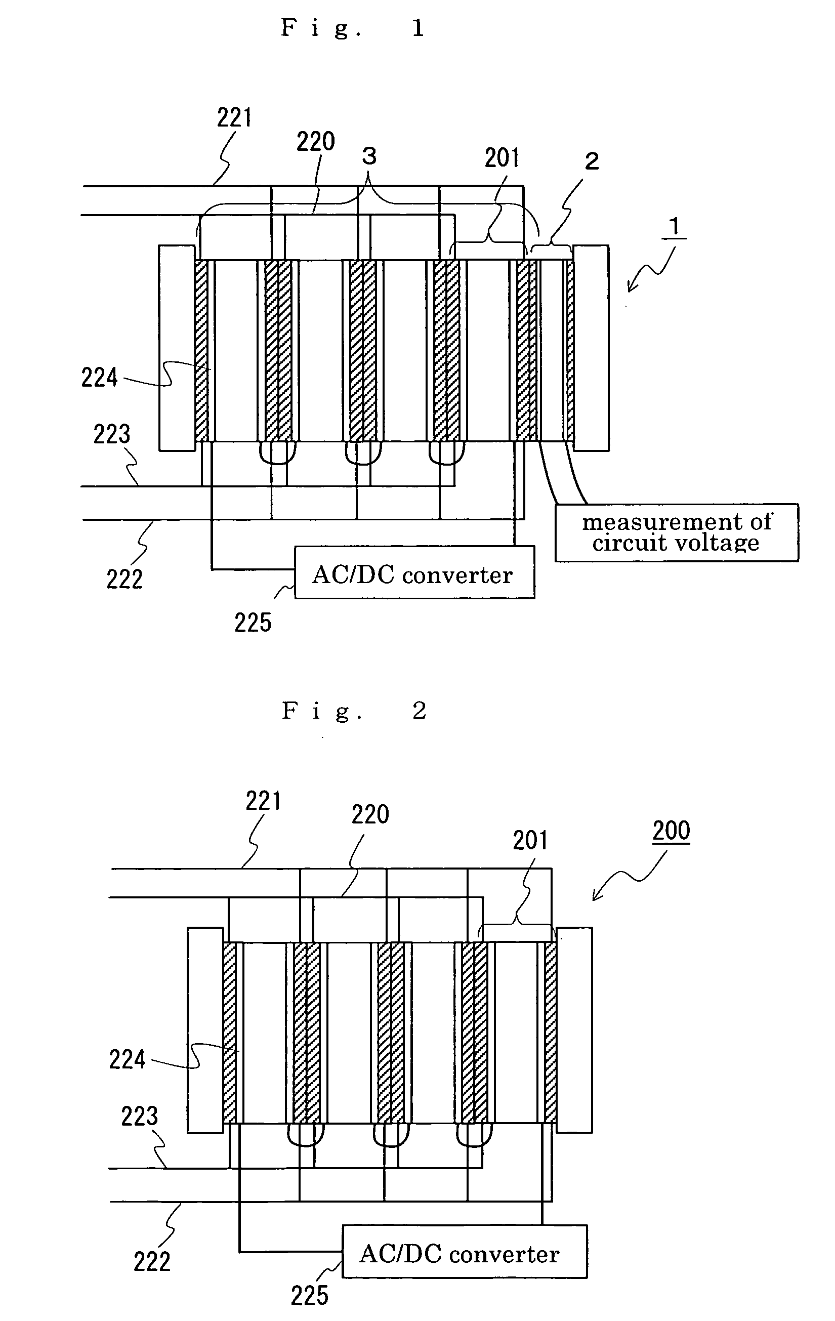
[0031] A redox flow battery of AC170 kW×8 hrs. was produced and the changes of the battery capacity with variation of temperature was monitored. For the test, the redox flow battery system as shown in FIGS. 3 and 4 was fabricated. Taken as the test sample No. 1-1 was a redox flow battery using the cell stack 1 comprising a total of five sets of cells, namely, four sets of sub-stacks 201 (main cell 3), each comprising twenty-five cells stacked in layers, not shown, and one set of auxiliary cell 2 comprising the same cell 1, as shown in FIG. 1. Taken as the test sample No. 1-2 was a redox flow battery using the cell stack 200 comprising four sets of sub-stacks 201 and having no auxiliary cell (the cell stack comprising the main cell only), as shown in FIG. 2. The operating conditions for the test are shown below. The test results are shown in TABLE 1.
[0032] Test Sample No. 1-1: The circuit voltage is constantly measured by the auxiliary cell so that the stop of charge ...
Example
TEST EXAMPLE 2
[0036] A redox flow battery of AC170 kW×6 hrs. was produced. When the charging rate of the main cell decreased, the auxiliary cell was charged. The basic configuration of the battery used in this example was the same as that of the redox flow battery taken as the test sample No. 1-1 used in the Test Example 1. The test was carried out in the following manner. When the circuit voltage as measured by the auxiliary cell reached 1.35V / cell, a direct-current power source additionally provided on the auxiliary cell was turned on to start the charging and discharging operation of the auxiliary cell.
[0037] It was found from the test results that when about 100 kWh was charged by the auxiliary cell in a constant current operation, the decreased charging rate of the main cell could be increased by the auxiliary cell, so that the main cell could keep on discharging to an extent corresponding to the electricity charged by the auxiliary cell. Then, the output capacity was nearly ...
Example
TEST EXAMPLE 3
[0039] Combination of the redox flow battery (AC170 kW×6 hrs.) produced in Test Example 2 with a wind generator was produced. When reduction occurred in charging rate of the main cell, a total output of the wind generator plus the redox flow battery was decreased. This test was carried out in the following manner. When the circuit voltage as measured by the auxiliary cell reached 1.37V / cell, the total output was decreased and the operation was continued until the circuit voltage reached 1.35V / cell. The specification of the wind generator used is given below.
[0044] It was found from the test results that the charging rate of the main cell could be increased by decreasing the total output, whereby the main cell could keep on discharging. Then, the output capacity was nearly 1,120 kWh. For comparison, the total output ...
PUM
Abstract
The invention provides an operating method of a redox flow battery capable of grasping a charging state of the battery more reliably to stabilize an output capacity of the battery. The method is for operating the redox flow battery comprising a cell stack 1 comprising a plurality of cells. A selected cell(s) in the cell stack 1, to and from which positive electrode electrolyte and negative electrode electrolyte are supplied and discharged and which is/are not normally connected to a DC/AC converter 225, is/are in the form of an auxiliary cell 2 used for measuring a charging rate of the electrolyte. Also, a stop of charge of a main cell 3 and a stop of discharge of the main cell 3 are controlled with reference to a circuit voltage obtained from the auxiliary cell 2. Since the auxiliary cell 2 is integrally incorporated in the cell stack 1, the charging state of the battery can be grasped reliably without stopping the charge/discharge operation of the main cell 3. Also, since the stop of charge of the main cell 3 and the stop of discharge of the same are controlled with reference to the measured circuit voltage, the output capacity can be stabilized.
Description
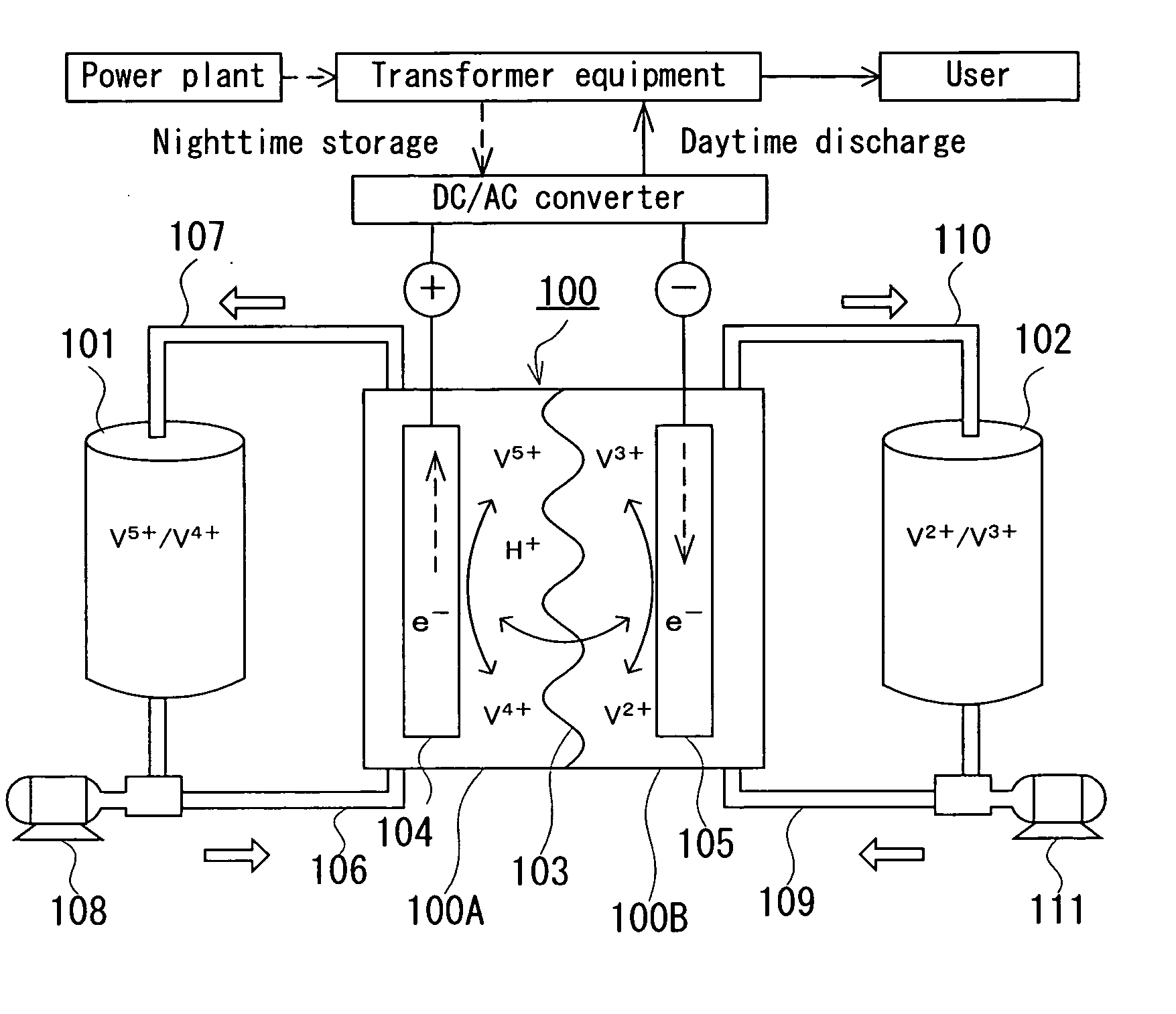
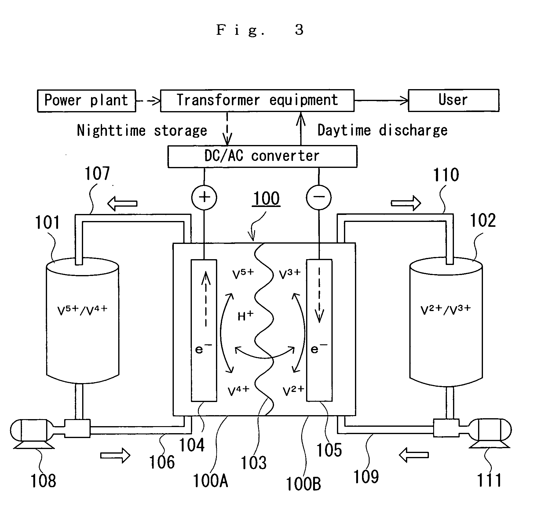
TECHNICAL FIELD [0001] The present invention relates to an operating method of a redox flow battery and to a cell stack of the same. More particularly, the present invention relates to an operating method of a redox flow battery capable of constantly grasping the state of charge to stabilize an output capacity most suitably, and to a cell stack of the redox flow battery most suitable for this operating method. BACKGROUND ART [0002] In general, redox flow batteries are used for load leveling or for countermeasure to voltage sag (momentary drop in voltage). FIG. 3 shows an explanatory view showing an operating principle of a redox flow secondary battery. This battery has a cell 100 which is separated into a positive electrode cell 100A and a negative electrode cell 100B by a membrane 103 of an ion-exchange membrane. A positive electrode 104 and a negative electrode 105 are contained in the positive electrode cell 100A and the negative electrode cell 100B, respectively. A positive elec...
Claims
Application Information
Patent Timeline
Application Date:The date an application was filed.
Publication Date:The date a patent or application was officially published.
First Publication Date:The earliest publication date of a patent with the same application number.
Issue Date:Publication date of the patent grant document.
PCT Entry Date:The Entry date of PCT National Phase.
Estimated Expiry Date:The statutory expiry date of a patent right according to the Patent Law, and it is the longest term of protection that the patent right can achieve without the termination of the patent right due to other reasons(Term extension factor has been taken into account ).
Invalid Date:Actual expiry date is based on effective date or publication date of legal transaction data of invalid patent.

