Insulated hot water storage tank for sink

a technology for hot water storage tanks and sinks, applied in water heaters, water installations, constructions, etc., can solve problems such as non-functional recirculating cooled hot water systems

Inactive Publication Date: 2005-08-04
PERMENTER JOHN B
View PDF13 Cites 20 Cited by
  • Summary
  • Abstract
  • Description
  • Claims
  • Application Information

AI Technical Summary

Benefits of technology

[0027] It is an object of the invention to provide improved elements and arrangements thereof for the purposes described which is inexpensive, dependable and fully effective in accomplishing its intended purposes.

Problems solved by technology

If the main water supply has insufficient pressure, the recirculating cooled hot water system is non-functional.

Method used


Image

  • Insulated hot water storage tank for sink
  • Insulated hot water storage tank for sink
  • Insulated hot water storage tank for sink

Examples


Embodiment Construction

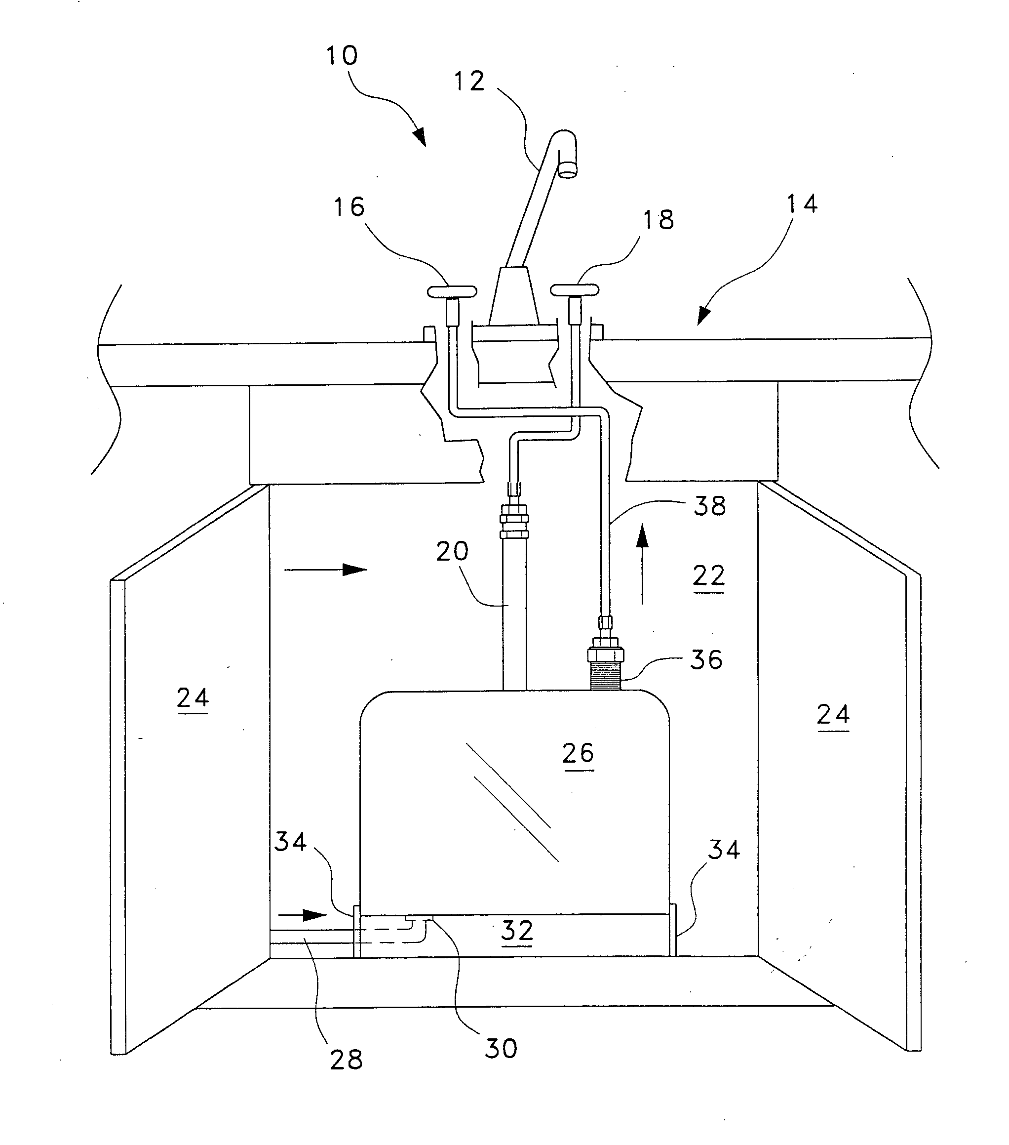
[0032] The present invention is illustrated in FIG. 1 as a hot water tank system 10 under a water faucet 12 of a kitchen sink 14 having a hot water valve 16, a cold water valve 18, and a cold water supply pipe 20. Inside the kitchen cabinet 22 with twin doors 24 open is the system 10 that could be applied also to a toilet sink, a bathtub, and the like. The system 10 comprises a metal or plastic hot water storage tank 26 of any shape, e.g., rectangular tank, having a hot water supply pipe 28 feeding hot water from the household water heater tank (not shown) to the influent nipple element 30. The tank 26 has a removable base portion 32 via clamps 34 for gaining access to the tank for cleaning purposes. The effluent nipple element 36 on the tank 26 is connected to an effluent pipe 38 supplying hot water to the water faucet 12.

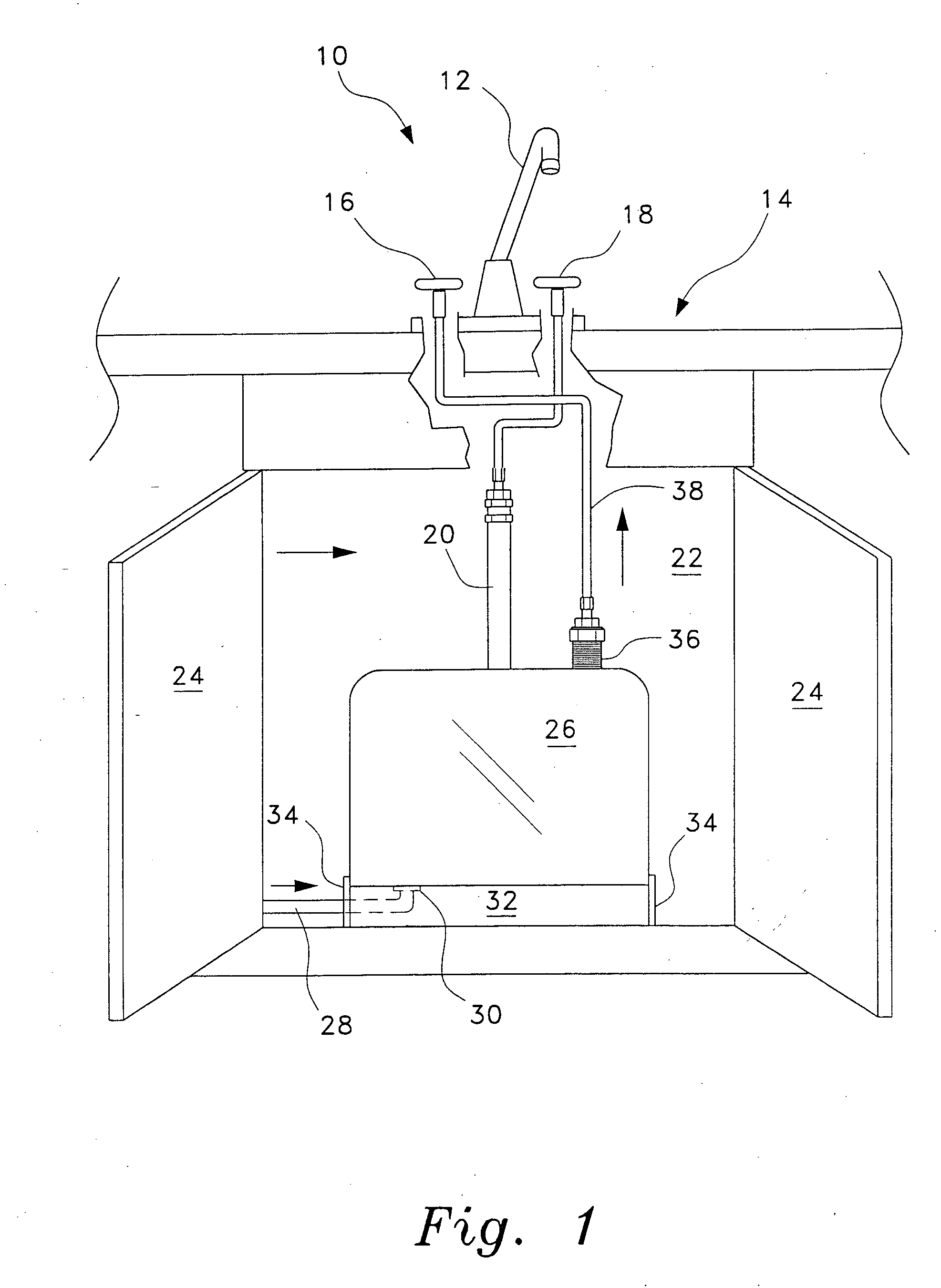
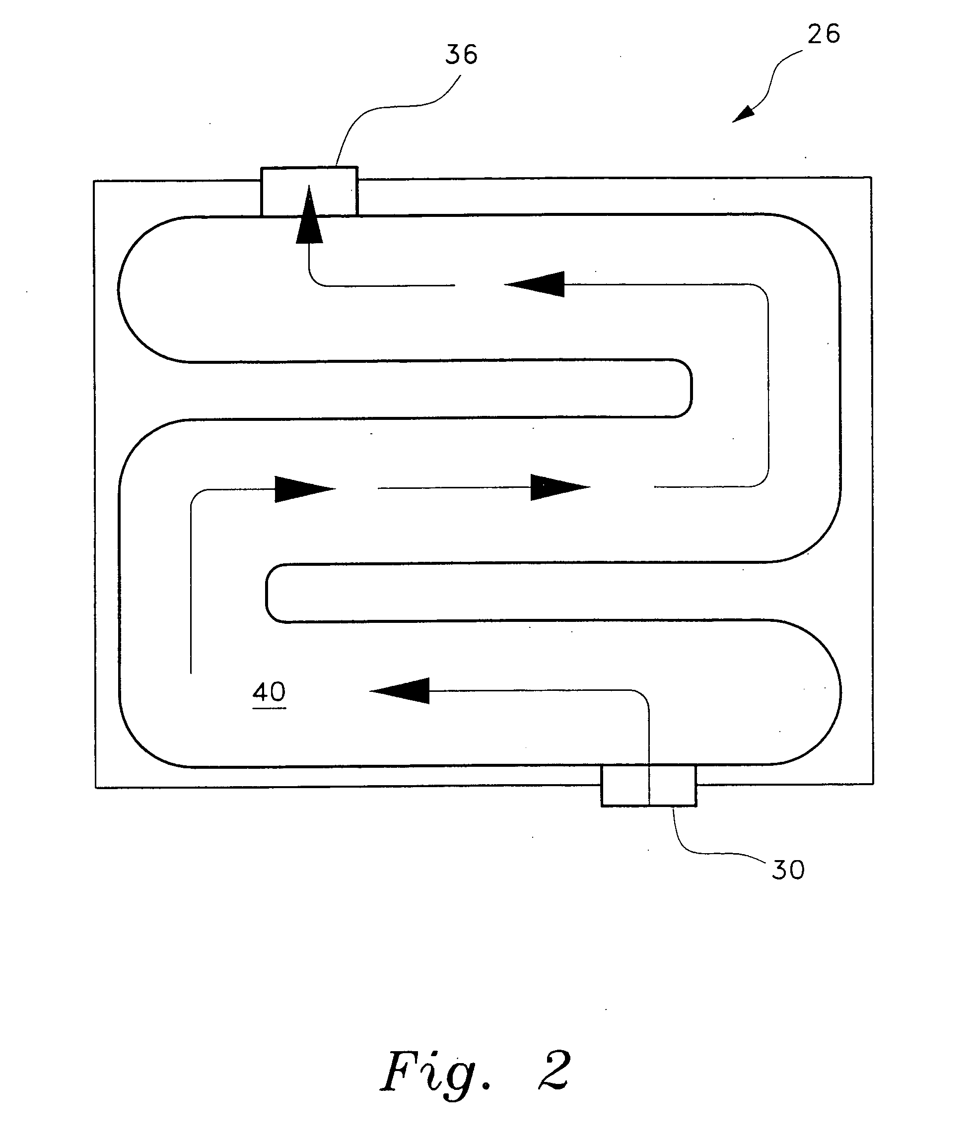
[0033]FIG. 2 shows a schematic cross-sectional view of the hot water storage tank 26 showing the hot water 40 flowing from the hot water influent nipple element ...


PUM


Abstract

A hot water storage tank having a capacity of approximately a quart to a gallon for a sink, a tub or the like is constructed of an insulated (fiber or vacuum) metal or plastic container including connections to a hot water influent pipe and an effluent pipe to the hot water faucet. This apparatus would eliminate the problem of wasting the cold water from the hot water faucet while waiting for the water to heat up.

Description

BACKGROUND OF THE INVENTION [0001] 1. Field of the Invention [0002] The present invention relates generally to plumbing systems. More specifically, the invention is an insulated hot water storage tank connected to the hot water supply line adjacent a hot water faucet. [0003] 2. Description of the Related Art [0004] The related art of interest describes hot water tanks, but does not disclose any hot water storage tank located under a sink. There is a need for a remote, but adjacent hot water tank to supply hot water immediately to the sink faucet. The relevant art will be discussed in the order of perceived relevance to the present invention. [0005] U.S. Pat. No. 4,160,461 issued on Jul. 10, 1979, to Marcel Vataru et al. describes a water and energy conservation system comprising a hot water storage tank connected between a hot water line and a hot water faucet. When the hot water faucet is turned on, the water in the hot water line is conducted into the reservoir where it accumulate...

Claims


Application Information

Patent Timeline
Patent Type & Authority Applications(United States)
IPC IPC(8): E03B1/04E03B11/02E03C1/02F24H1/20F24H9/02
CPCF24H1/202E03C1/044
Inventor PERMENTER, JOHN B.
Owner PERMENTER JOHN B
Why Eureka
Try Eureka