Filter cartridge and manifold for a water purification system

a filter cartridge and manifold technology, applied in the direction of filtration separation, multi-stage water/sewage treatment, separation process, etc., can solve the problems of undesired filter element removal, significant water leakage, and potential damage to adjoining flooring materials, so as to facilitate the removal and replacement of filter cartridges that are substantially fail-safe and substantially drip-free, and quick and easy respective connection

Inactive Publication Date: 2005-08-04
ZOHAR WATERWORKS
View PDF9 Cites 95 Cited by
  • Summary
  • Abstract
  • Description
  • Claims
  • Application Information

AI Technical Summary

Benefits of technology

[0007] In accordance with the invention, a combined filter cartridge and manifold are provided for use in a water purification system or the like, to facilitate substantially fail-safe and substantially drip-free filter cartridge removal and replacement. The manifold is coupled to a suitable water supply and includes inlet and outlet fittings for quick and easy respective connection with water inlet and outlet ports on the filter cartridge. A pivotal manifold cap is mounted on the manifold for pivoting movement between a normal closed or lowered position overlying and retaining the filter cartridge in proper connected relation with the manifold fittings and the water supply, and an open or raised position for disconnection of the water supply before permitting filter cartridge separation from the manifold. Check valves at the cartridge inlet and outlet ports prevent water leakage from the removed cartridge. Upon installation of a replacement filter cartridge, the manifold cap is returned to the initial closed position, with cooperating cam elements on the manifold cap and filter cartridge drawing the cartridge inlet / outlet ports into secure connection with the manifold inlet / outlet fittings before reconnection with the water supply.
[0008] In one preferred construction, the manifold includes a support bracket adapted for wall mounting at an under-counter location or the like, and including a pair of bracket arms for seated support of a pair of cam pins projecting outwardly from opposed sides of the filter cartridge. Positioning of a filter cartridge with said cam pins supported on the bracket arms orients the cartridge inlet / outlet ports in alignment with the manifold inlet / outlet fittings for correct, substantially fail-safe flow coupling therewith. The cartridge inlet / outlet check valves are adapted to open upon connection with the manifold inlet / outlet fittings, and to close upon separation therefrom. When the manifold cap is in the raised or open position, the support bracket is sufficiently exposed for filter cartridge removal and replacement relative to the bracket arms. Upon displacement of the manifold cap toward the lowered or closed position, a cam track defined by the manifold cap engages the cartridge cam pins to carry the cartridge inlet / outlet ports into proper and secure flow-coupled connection with manifold inlet / outlet fittings, followed by opening connection with the water supply. In this lowered or closed position, the manifold cap overlies at least the portion of the filter cartridge including the inlet / outlet ports and the associated manifold inlet / outlet fittings to positively block and prevent filter cartridge removal from the manifold.

Problems solved by technology

Unfortunately, shutting off the incoming water flow requires the user to locate and properly operate an inflow shut-off valve before a filter element is removed.
Many prior manifold systems designed for quick and easy filter element changeover have not provided any means for safeguarding against undesired filter element removal before the incoming water supply is turned off.
In this regard, filter element removal without first turning off the water supply can result in significant water leakage and potential damage to adjoining flooring materials and the like.

Method used


Image

  • Filter cartridge and manifold for a water purification system
  • Filter cartridge and manifold for a water purification system
  • Filter cartridge and manifold for a water purification system

Examples


Embodiment Construction

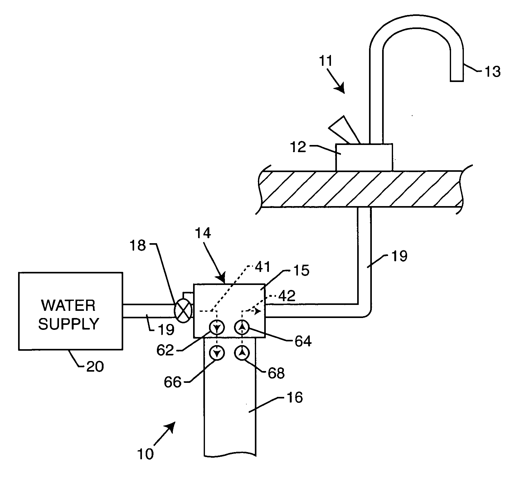
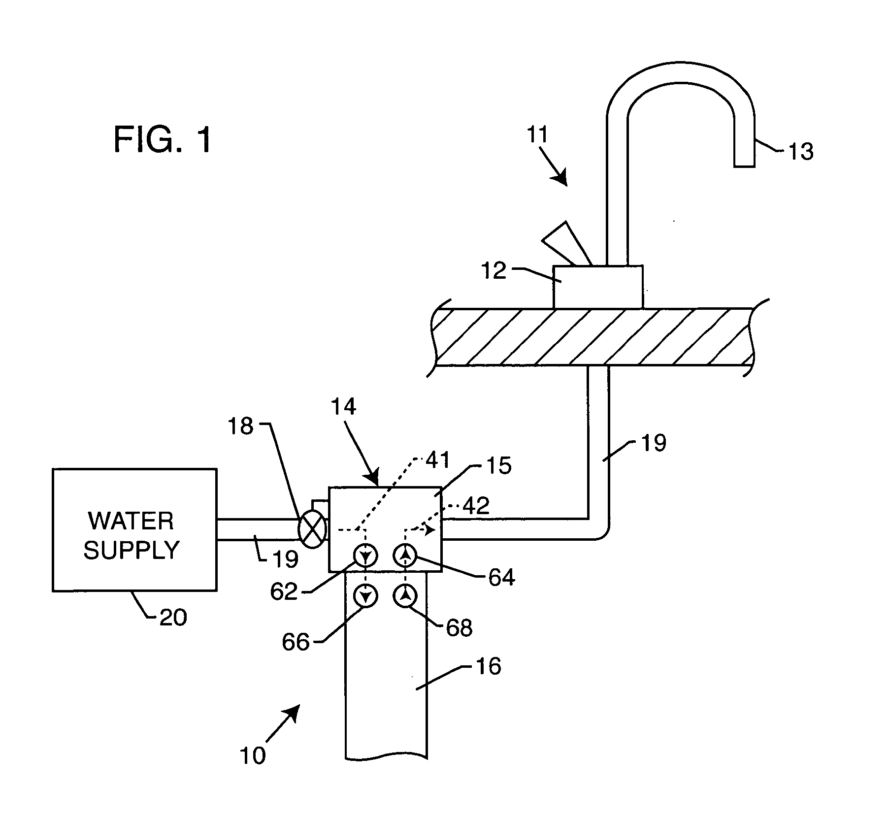
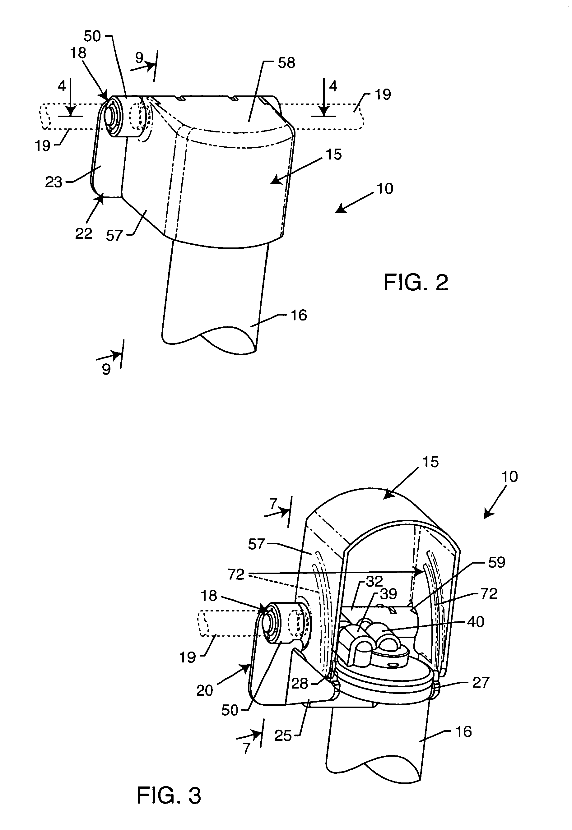
[0032] As shown in the exemplary drawings, a combined filter cartridge and manifold system referred to generally in FIG. 1 by the reference numeral 10 is provided for providing relatively purified water for dispensing by means of a faucet 11 or the like including (as shown) a suitable faucet valve 12 for regulating dispense water flow through a faucet spout 13 or the like. The cartridge and manifold system 10 includes a manifold 14 having a pivotally movable manifold cap 15 for normally retaining and supporting a removable filter cartridge 16 to produce purified water for dispensing, as viewed in FIGS. 2 and 9. The manifold cap 15 can be raised from a normally closed position (FIGS. 2 and 9) to an open position (FIGS. 3 and 7) initially closing a water supply valve 18 and then exposing and releasing the filter cartridge 16 for quick and easy removal and replacement. The manifold 14 and the filter cartridge 16 includes one-way check valves which close upon cartridge removal from the ...


PUM

PropertyMeasurementUnit
rotary angleaaaaaaaaaa
sliding displacementaaaaaaaaaa
displacementaaaaaaaaaa

Abstract

A combined filter cartridge and manifold for use in a water purification system or the like, to facilitate substantially drip-free filter cartridge removal and replacement. The filter cartridge includes water inlet and outlet ports for respective connection with inlet and outlet fittings on the manifold. A pivoting manifold cap normally overlies and retains the filter cartridge in connected relation with the manifold fittings and a water supply coupled to the manifold. Pivoting movement of the manifold cap toward an open position shuts off the water supply and then permits filter cartridge separation from the manifold, with check valves at the manifold inlet / outlet fittings and cartridge inlet / outlet ports preventing significant water leakage. Upon installation of a replacement filter cartridge and return movement of the manifold cap to the initial closed position, cam elements on the manifold cap and filter cartridge draw the cartridge inlet / outlet ports into secure slide-on connection with the manifold inlet / outlet fittings before resuming connection with the water supply.

Description

[0001] This application claims the benefit of U.S. Provisional Application 60 / 541,844, filed Feb. 3, 2004.BACKGROUND OF THE INVENTION [0002] This invention relates generally to water purification systems of the type having one or more filter elements for producing a supply of filtered or relatively purified water, wherein the filter elements are supported by a filter manifold for relatively quick and easy removal and replacement. More particularly, this invention relates to an improved water purification system wherein each filter cartridge is adapted for removal and replacement in a substantially fail-safe manner, with little or no risk of undesired water spillage in the course of filter cartridge changeover, or from a removed filter cartridge. [0003] Water purification systems are generally well known in the art for producing a relatively purified water supply used for drinking, cooking, etc. Such purification systems commonly employ one or more filter elements connected to an inc...

Claims


Application Information

Patent Timeline
Patent Type & Authority Applications(United States)
IPC IPC(8): B01D35/153C02F9/00
CPCB01D35/153B01D2201/302B01D2201/4023B01D2201/4046C02F1/001C02F2201/006C02F9/005B01D35/301C02F9/20
Inventor BURROWS, BRUCE D.CHANEY, DAVID B.BUSICK, LOUIS M.
Owner ZOHAR WATERWORKS
Why Eureka
Try Eureka