Brake device for a two-wheeled motor vehicle, and method of using same

a two-wheeled motor vehicle and brake device technology, applied in the direction of cycle brakes, vehicle components, cycle equipment, etc., can solve the problem of rider discomfort, achieve the effect of improving braking operation, maintaining braking force distribution to the front wheel, and improving braking efficiency

Inactive Publication Date: 2005-08-04
HONDA MOTOR CO LTD
View PDF6 Cites 17 Cited by
  • Summary
  • Abstract
  • Description
  • Claims
  • Application Information

AI Technical Summary

Benefits of technology

[0009] In such a case, until the vehicle is stopped after the braking operation on the rear wheel is started, if a brake manipulated variable is constant, braking force distribution to the front wheel is maintained constant. Moreover, since the braking force distribution characteristics are set for each vehicle speed, when the rear wheel braking operation is performed from a high-speed driving state, for example, the front wheel side braking force distribution is increased to improve braking efficiency. When the rear wheel braking operation is performed at low speed, such as when passing through between vehicles, the front wheel side braking force distribution is reduced (including a front wheel distribution of zero). Thus, it is possible to realize braking without affecting a vehicle driving operation.
[0010] In the invention described above, the front wheel braking means is consistently controlled by the braking force distribution characteristics depending on the vehicle speed when the rear wheel braking operation is started. Thus, it is possible to provide an improved feeling of braking operation at the time of the rear wheel braking operation while maintaining high braking efficiency in the high-speed driving, and to satisfy different requirements depending on conditions of the braking operation such as the ensuring of operability in passing through between vehicles.

Problems solved by technology

Consequently, when the braking device is applied to a motorcycle of which maximum speed is fast, there may occur a deceleration change (see FIG. 17) of such an extent that the rider feels uncomfortable due to the change in the front / rear braking force distribution during deceleration from a high-speed driving state.

Method used


Image

  • Brake device for a two-wheeled motor vehicle, and method of using same
  • Brake device for a two-wheeled motor vehicle, and method of using same
  • Brake device for a two-wheeled motor vehicle, and method of using same

Examples


Embodiment Construction

[0032] Next, with reference to the drawings, an embodiment of the present invention will be described.

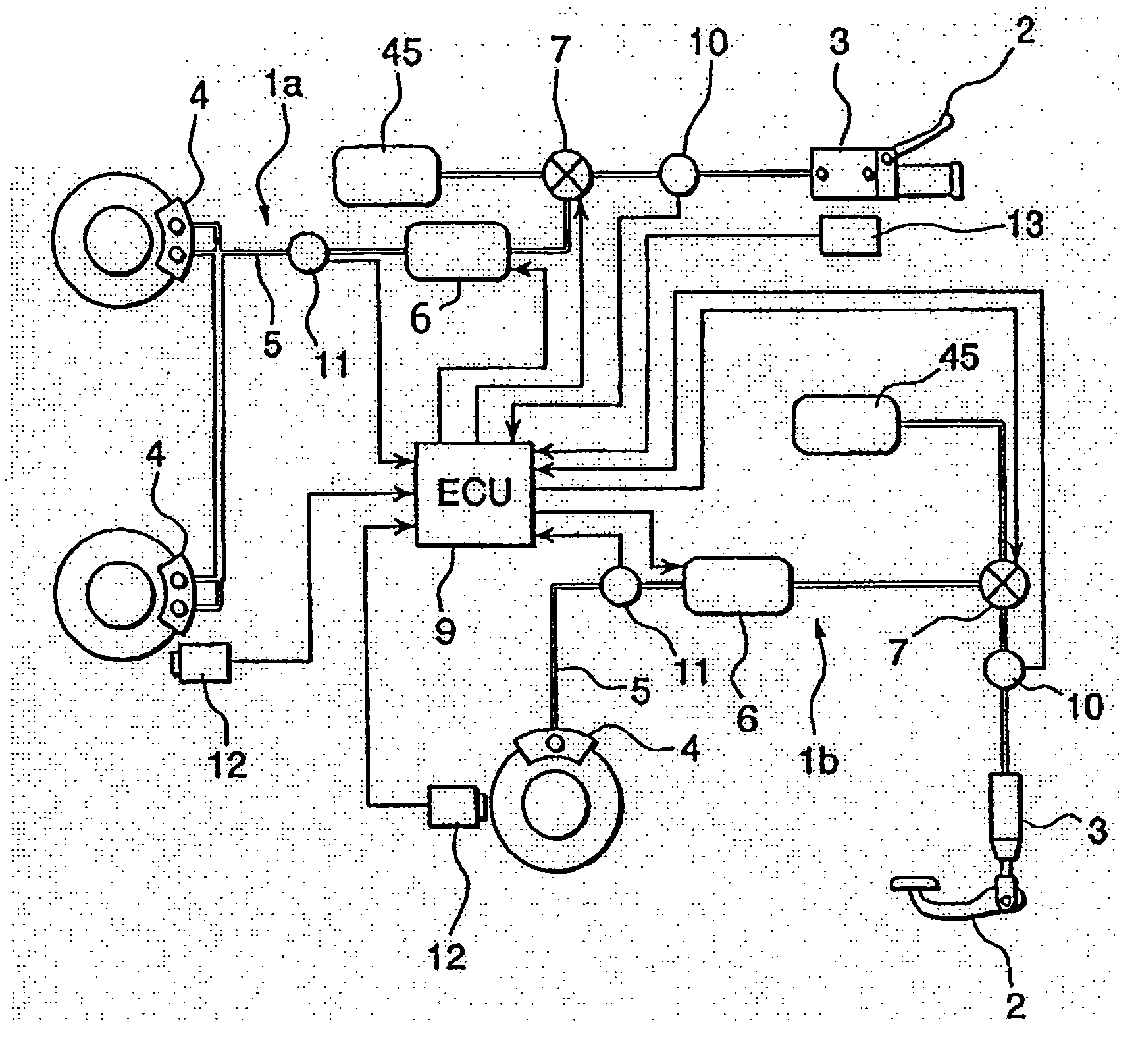
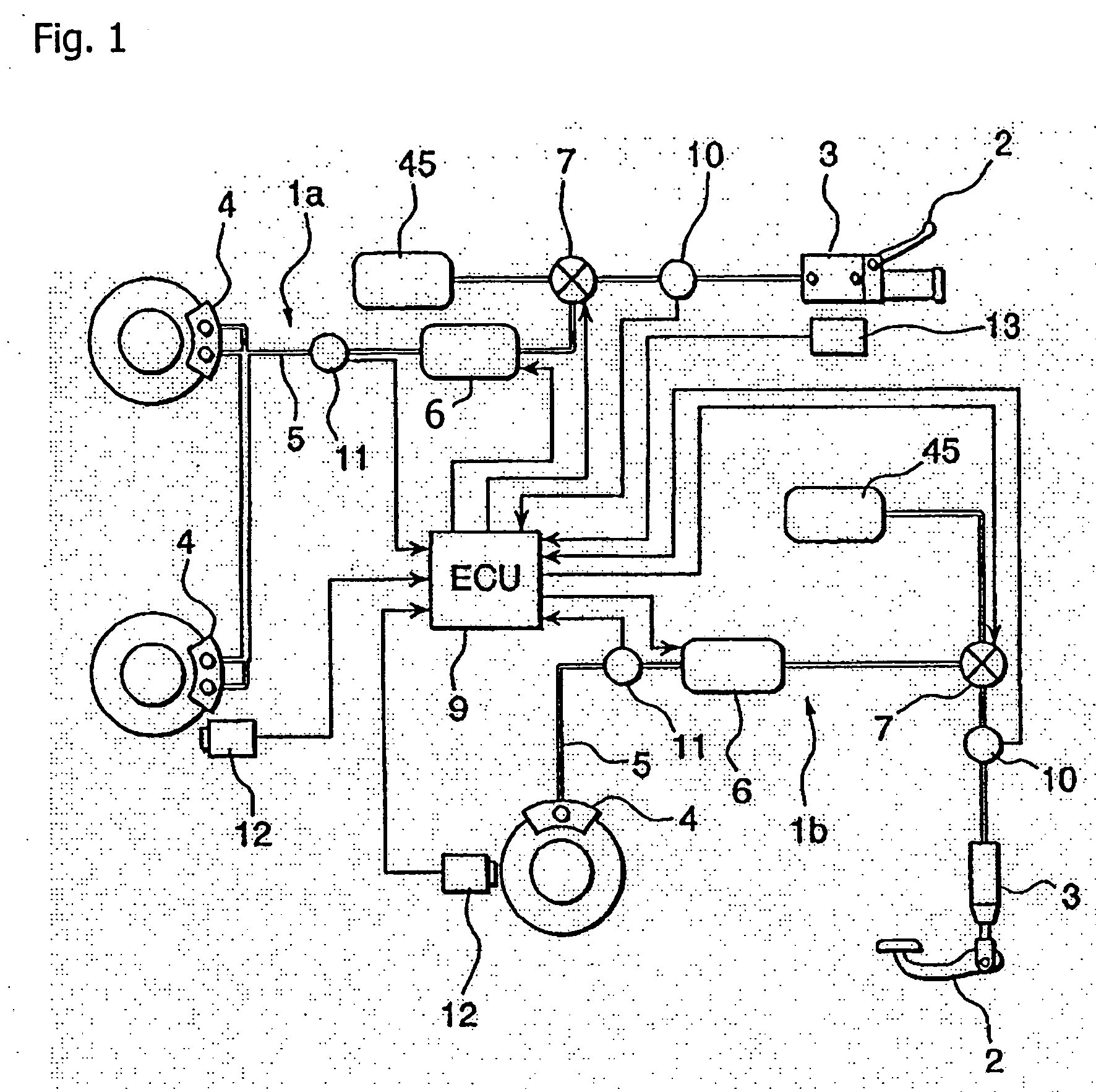
[0033]FIG. 1 shows an entire configuration of an embodiment of a braking device according to the present invention. As shown in FIG. 1, the braking device of this embodiment includes a front wheel side brake circuit 1a and a rear wheel side brake circuit 1b, which are independent of each other. In the case of this embodiment, the brake circuits 1a and 1b on the front and rear wheels are different from each other in that a brake operating unit 2 on the front wheel is formed of a lever, and a brake operating unit 2 on the rear wheel is formed of a pedal. However, both brake circuits are approximately the same in other basic configurations. In the following concrete description of a circuit configuration, only the front wheel side brake circuit 1a will be described in detail. As to the rear wheel side brake circuit 1b, parts that are the same as those of the front wheel side brake cir...


PUM


Abstract

A braking device for a motorcycle, in which front wheel braking means is operated in conjunction with a braking operation on a rear wheel, eliminates a rapid change in front / rear braking force distribution at the time of a rear wheel braking operation so as to consistently allow a rider to feel a smooth braking operation. Braking force distribution characteristics on the rear and front wheels are previously set for each vehicle speed. When the braking operation on the rear wheel is performed, a brake caliper on the front wheel is controlled so as to maintain braking force distribution characteristics corresponding to a vehicle speed when the operation is started.

Description

CROSS-REFERENCE TO RELATED APPLICATIONS [0001] The present invention claims priority under 35 USC 119 based on Japanese patent application No. 2004-024043, filed on Jan. 30, 2004. The subject matter of these priority documents is incorporated by reference herein. BACKGROUND OF THE INVENTION [0002] 1. Field of the Invention [0003] The present invention relates to a braking device of a two-wheeled motor vehicle, and more particularly to a braking device for a motorcycle, which can operate front wheel braking means in conjunction with a braking operation on a rear wheel. [0004] 2. Description of the Background Art [0005] A braking device for a motorcycle which can operate front wheel braking means in conjunction with a braking operation on a rear wheel is described in Japanese Patent Laid-Open No. Hei 8 (1996)-150925. In the braking device described Japanese Patent Laid-Open No. Hei 8 (1996)-150925, respective brake operating units of front and rear wheels and wheel braking means are c...

Claims


Application Information

Patent Timeline
Patent Type & Authority Applications(United States)
IPC IPC(8): B60T8/26B60T11/10B60T13/00B62L3/08
CPCB60T11/101B60T8/261
Inventor TANI, KAZUHIKONAKAYAMA, MASANOBUNISHIMOTO, YUKIMASA
Owner HONDA MOTOR CO LTD
Why Eureka
Try Eureka