Battery management system and apparatus

a technology of battery management system and equipment, applied in secondary cell servicing/maintenance, instruments, nuclear elements, etc., can solve the problems of large size of stationary batteries, large discrepancy between design life and actual life, and limited shelf life and useful life, so as to facilitate data transfer and increase voltage and output power

Active Publication Date: 2005-08-04
ASKALITY LLC
View PDF5 Cites 59 Cited by
  • Summary
  • Abstract
  • Description
  • Claims
  • Application Information

AI Technical Summary

Benefits of technology

The OMS™ is a system that helps manage large batteries used in stationary applications. It uses special tags on each battery, which are scanned by a testing device to collect data about each battery. This data is then stored on a computer and can be viewed on a website. The system helps companies manage these batteries that are perishable and spread out over a large area.

Problems solved by technology

The patent text describes a system and method for managing large stationary batteries used for backup power in widely dispersed locations. The technical problem addressed by the invention is the difficulty of managing these perishable, expensive, and geographically dispersed assets, which are also hazardous to the environment and require strict documentation requirements. The invention provides a comprehensive solution comprising battery tags, a battery testing and data acquisition device, and a web-based software platform for managing a large number of these assets.

Method used


Image

  • Battery management system and apparatus
  • Battery management system and apparatus
  • Battery management system and apparatus

Examples


Embodiment Construction

[0024] The invention provides and coordinates battery testing, maintenance, installation, fulfillment and disposal of batteries, and is capable of performing these functions over a wide geographical area. It seamlessly integrates these services via the BatteryCorp BC-T2000 tester and the OMS™ web based platform. This innovative solution helps companies improve their backup power systems while reducing costs.

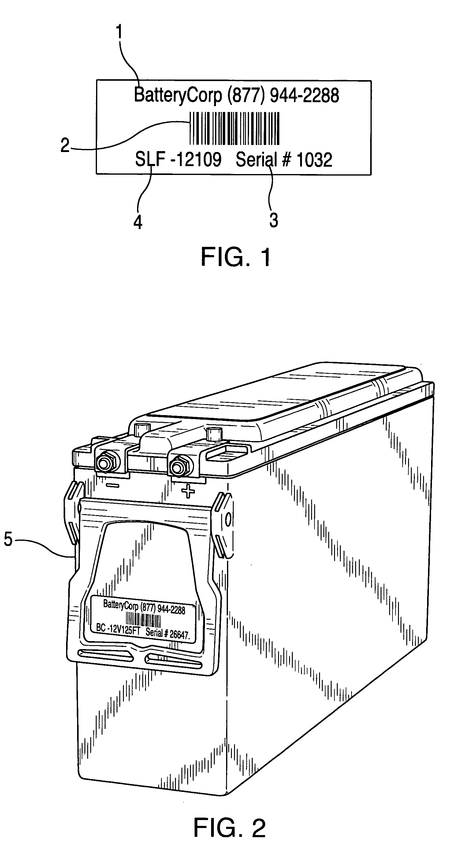
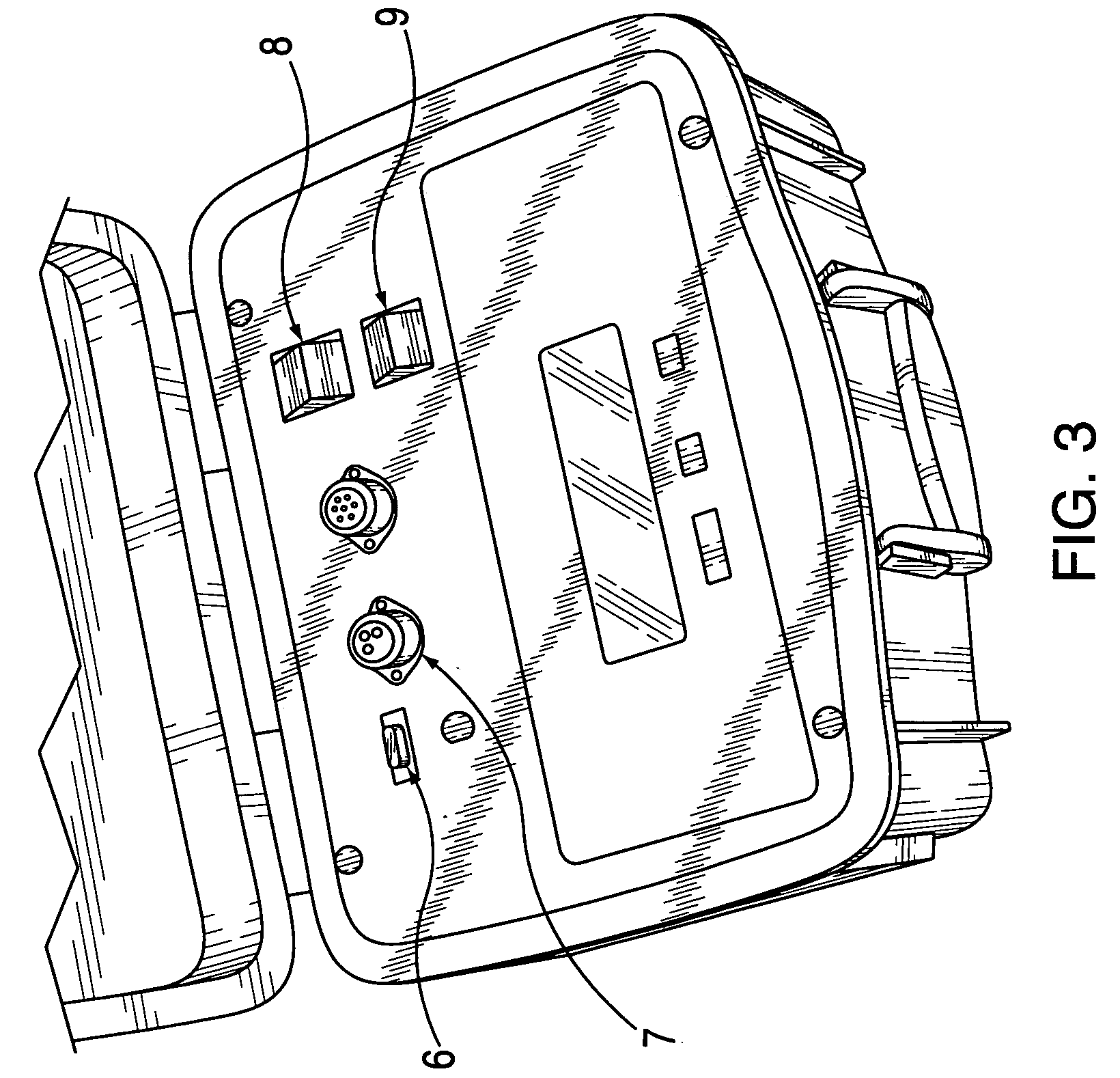
[0025]FIG. 1 shows a preferred Mega-Tag to be associated with an individual battery. The tag is associated with a particular battery unit, so that the unique identification number embedded in the tag is consistently associated with that particular battery. Preferably to assure such continued association, the Mega-Tag is affixed to the exterior casing of the battery (5) with an adhesive, as shown in FIG. 2.

[0026] Mega-Tags are preferably bar coded labels that contain a unique identifier for the associated battery. The tag shown in FIG. 1 has, preferably, the following informatio...


PUM


Abstract

The invention relates to the management of large stationary batteries. The invention is a comprehensive process for the management of stationary batteries that are used for backup power and are deployed in widely dispersed locations. The OMS™ (Optimization Management System) solution is comprised of Mega-Tags (preferably serialized bar-coded identification labels), a battery testing and data acquisition device, and web-based software. The OMS™ system employs algorithmic testing to determine whether a particular battery unit needs to be replaced or whether it can be advantageously redeployed. These components work together to provide a platform for managing a large number of perishable, expensive, and geographically dispersed assets.

Description


Claims


Application Information

Patent Timeline
Owner ASKALITY LLC
Why Eureka
Try Eureka