Apparatus and method for detecting a predetermined pattern on a moving printed product

a technology of printed products and apparatus, applied in the field of apparatus and methods for detecting predetermined patterns on moving printed products, to achieve the effect of precise timing

Active Publication Date: 2005-08-04
GRAPHO METRONIC MESS UND REGELTECHN GMBH & CO
View PDF2 Cites 8 Cited by
  • Summary
  • Abstract
  • Description
  • Claims
  • Application Information

AI Technical Summary

Benefits of technology

[0005] In view of the foregoing, it is an object of the invention to provide an apparatus and method with which a predetermined pattern of small dimensions on a moving printed product can be detected reliably in spite of any possible lateral position deviation of the printing material, and its occurrence can be signalled with precise timing.

Problems solved by technology

However, the aforementioned specification contains no more specific statements relating to the implementation and internal functioning of the sensor in question.
However, this is inconsistent with the endeavour previously mentioned to have the smallest possible area required for the pattern to be provided outside the subject merely for control purposes.

Method used


Image

  • Apparatus and method for detecting a predetermined pattern on a moving printed product
  • Apparatus and method for detecting a predetermined pattern on a moving printed product
  • Apparatus and method for detecting a predetermined pattern on a moving printed product

Examples


Embodiment Construction

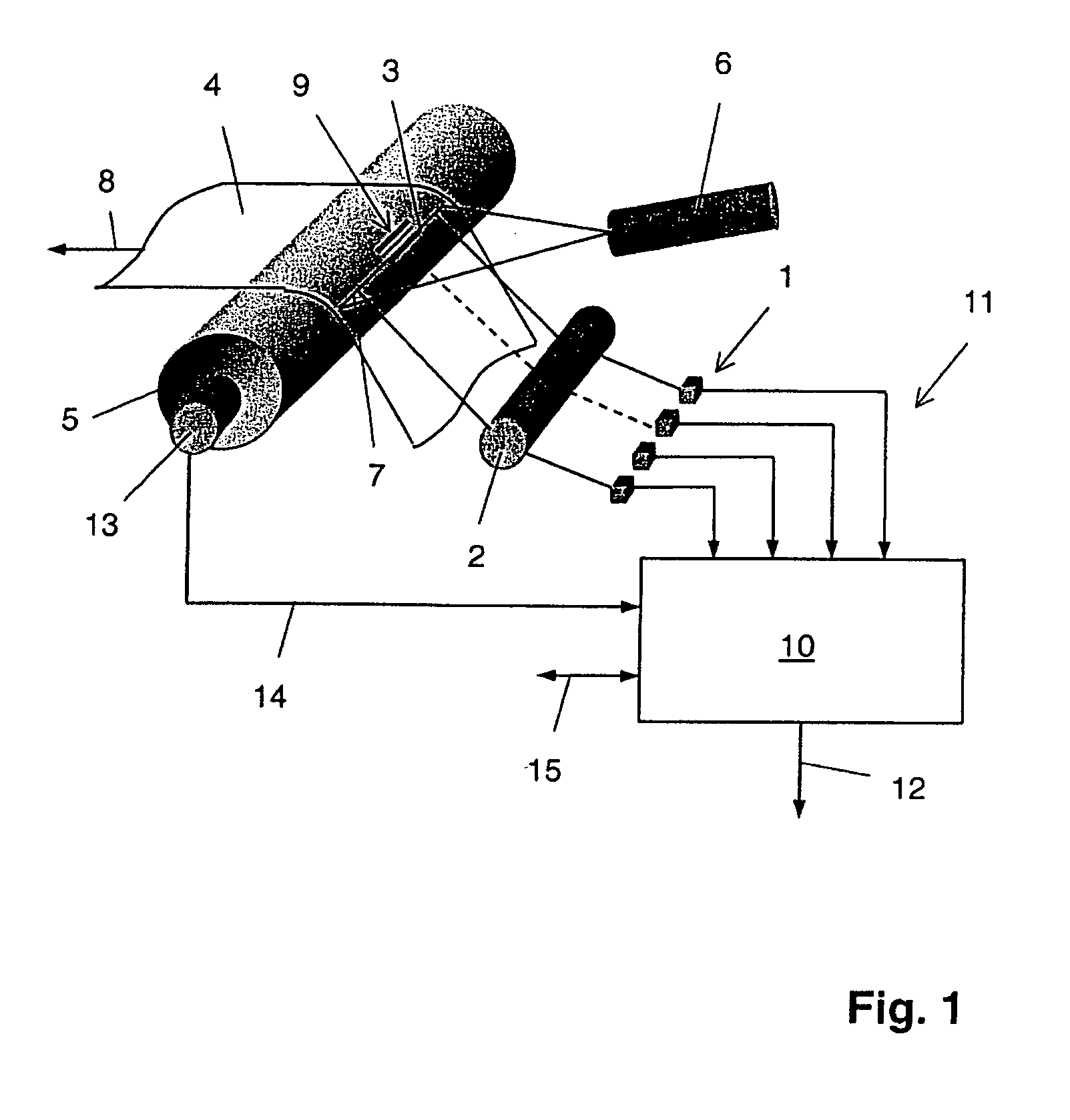
[0023] As FIG. 1 shows, an apparatus according to the invention has an arrangement 1 comprising a plurality of optoelectronic sensors, which are arranged linearly beside one another in a fixed spacing grid. The sensor arrangement 1 can be an arrangement 1 of discrete photodiodes on a printed circuit board, but also an integrated line sensor 1. In the case of the latter, there must be the possibility of reading the individual sensor elements in parallel, in order that a sufficiently high data rate can be achieved. By means of imaging optics 2 in the form of a cylindrical lens whose axis runs parallel to the line defined by the arrangement of the sensors 1, a narrow strip 3 of a printed product 4 is projected onto the sensor arrangement 1.

[0024] In order to maintain a constant distance from the lens 2 and the sensor arrangement 1, the printed product 4 is tensioned over a roller 5, whose axis is likewise parallel to the sensor arrangement 1. The roller 5 is a deflection roller 5 in a...


PUM

PropertyMeasurementUnit
moving speedaaaaaaaaaa
compositionaaaaaaaaaa
frequencyaaaaaaaaaa

Abstract

An apparatus and method for detecting a relatively narrow predetermined pattern, such as a trigger mark, on a moving printed product uses a plurality of sensor elements arranged linearly in an array and a switching apparatus for selecting a properly located subset of the sensor elements for detecting the predetermined pattern. During the operation of the apparatus, only those signals from sensors in the selected subset are checked continuously for the occurrence of a signal pattern corresponding to the predetermined pattern. Each time the predetermined signal pattern is found in the output signal from a sensor within the selected subset, a detection signal is generated. The lateral shifting of the predetermined pattern over time may be monitored by the selected sensors, and the selection of the subset of sensors for the continuous evaluation may be changed in response to the lateral shifting.

Description

FIELD OF THE INVENTION [0001] This invention relates to an apparatus and method for detecting a predetermined pattern on a moving printed product, and more particularly to an arrangement of optical sensor elements for detecting a predetermined pattern, such as trigger mark, on a moving printed product. BACKGROUND OF THE INVENTION [0002] DE 102 08 286 A1 discloses an electronic image evaluation device and an evaluation method in which a printed product is conveyed past the device and, during its movement, images of predetermined extracts of the printed product are acquired and evaluated. In order to trigger the image acquisition at the respectively correct time, a sensor is provided which outputs a synchronization signal when it detects a predetermined reference marking on the printed product. The extracts of the printed product to be acquired have known positions in relation to the reference marking, so that the correct triggering time for the image acquisition can be determined by ...

Claims


Application Information

Patent Timeline
Patent Type & Authority Applications(United States)
IPC IPC(8): B41F33/00B41F33/14G01N21/93G06K9/00G06K9/82
CPCB41F33/0081
Inventor LAMPERSBERGER, FRANZ
Owner GRAPHO METRONIC MESS UND REGELTECHN GMBH & CO
Why Eureka
Try Eureka