Fitting construction and developer holding unit and image forming apparatus that use the fitting construction

a technology of fitting construction and image forming apparatus, which is applied in the direction of caps, instruments, applications, etc., can solve the problems of high cost, increased number of parts for sealing methods using sponges, and high cost of molded parts

Active Publication Date: 2005-08-04
OKI ELECTRIC IND CO LTD
View PDF8 Cites 7 Cited by
  • Summary
  • Abstract
  • Description
  • Claims
  • Application Information

AI Technical Summary

Benefits of technology

[0008] An object of the invention is to provide a sealed fitting construction that uses injection molding that is simple, the fitting construction requiring a less number of parts and therefore being formed at low cost.

Problems solved by technology

However, the aforementioned construction suffers from the following problems.
This leads to expensive molded parts.
A sealing method that uses a sealing material such as sponge requires an increased number of parts, and is therefore costly.

Method used


Image

  • Fitting construction and developer holding unit and image forming apparatus that use the fitting construction
  • Fitting construction and developer holding unit and image forming apparatus that use the fitting construction
  • Fitting construction and developer holding unit and image forming apparatus that use the fitting construction

Examples


first embodiment

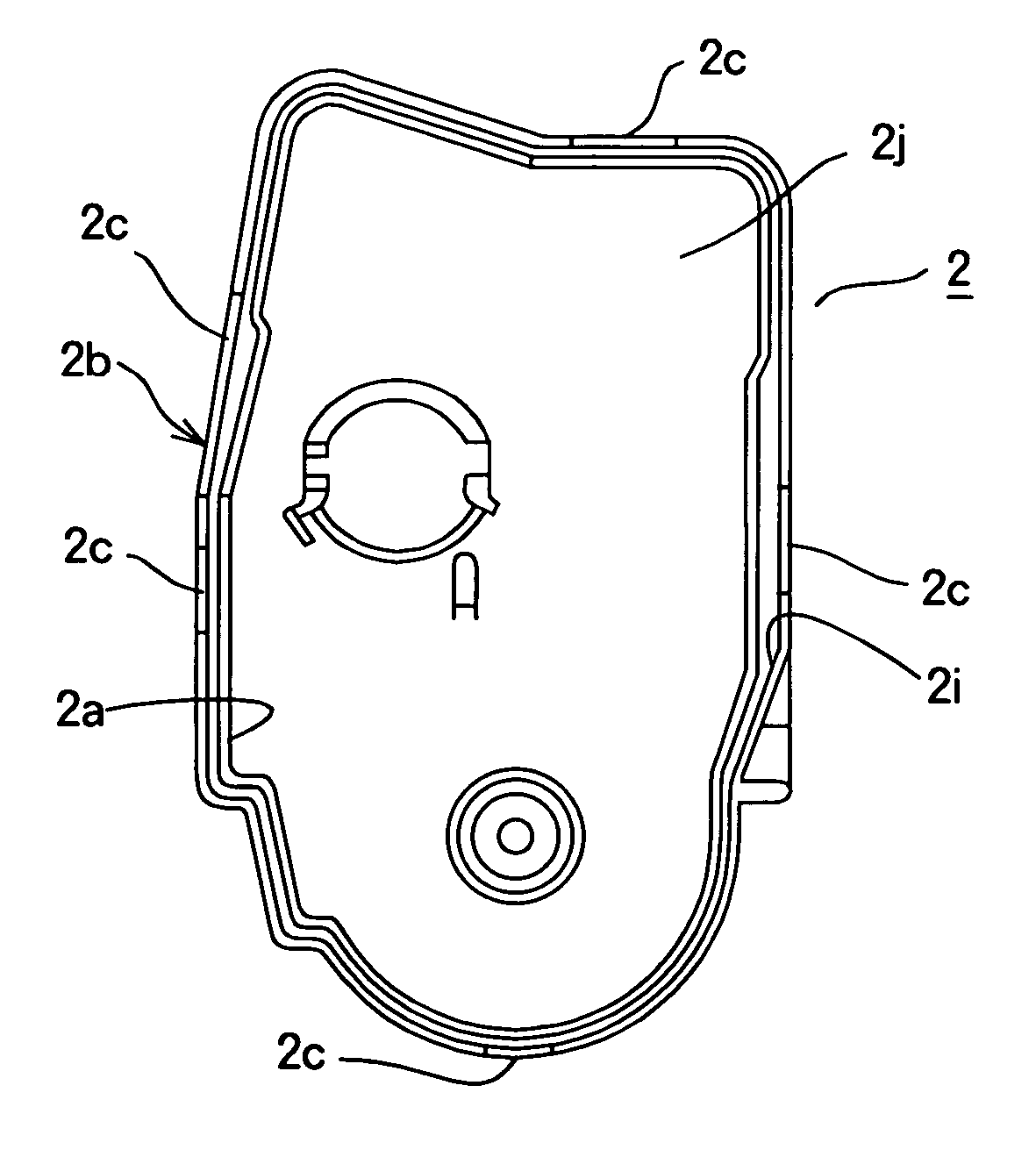
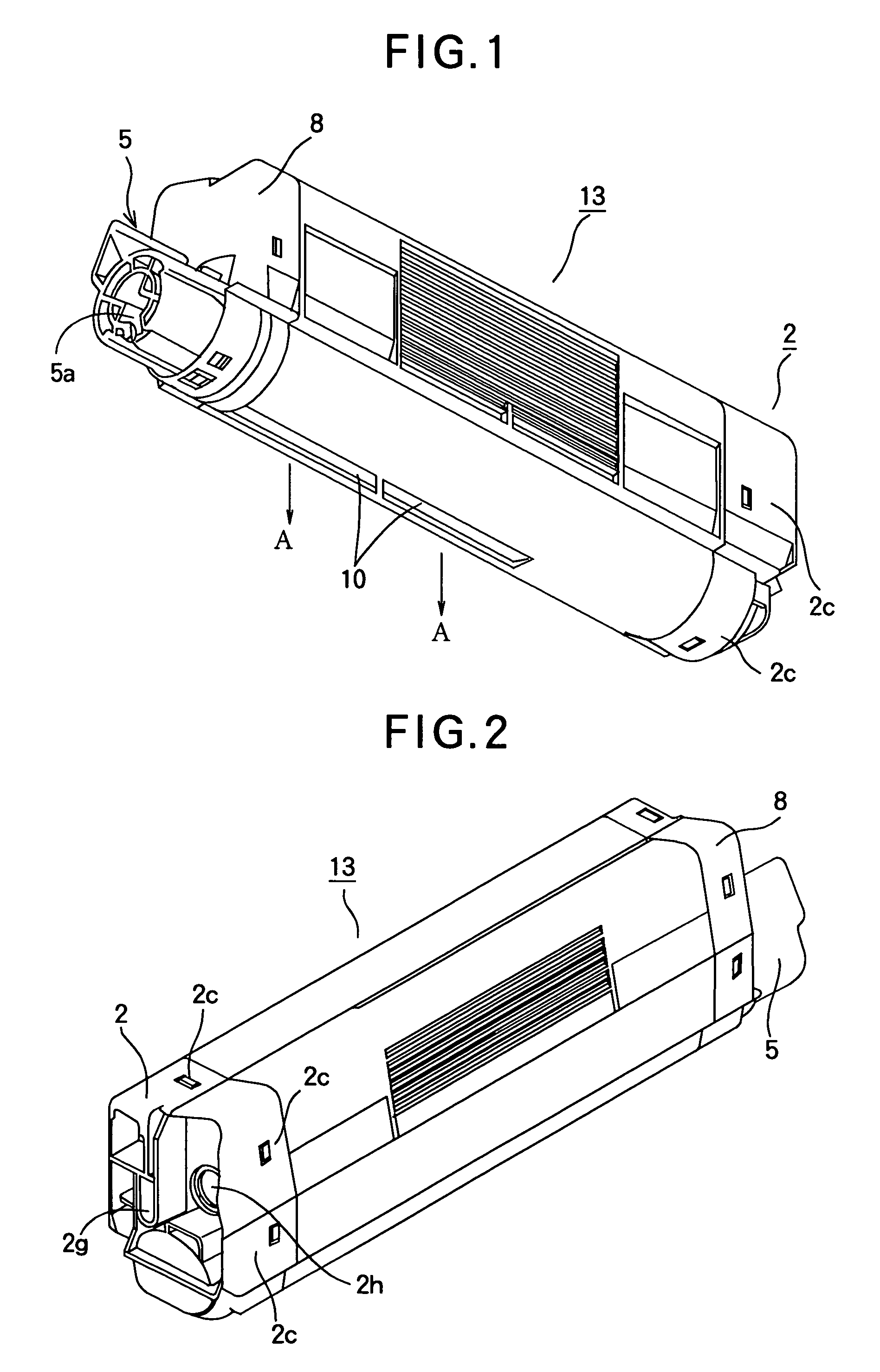
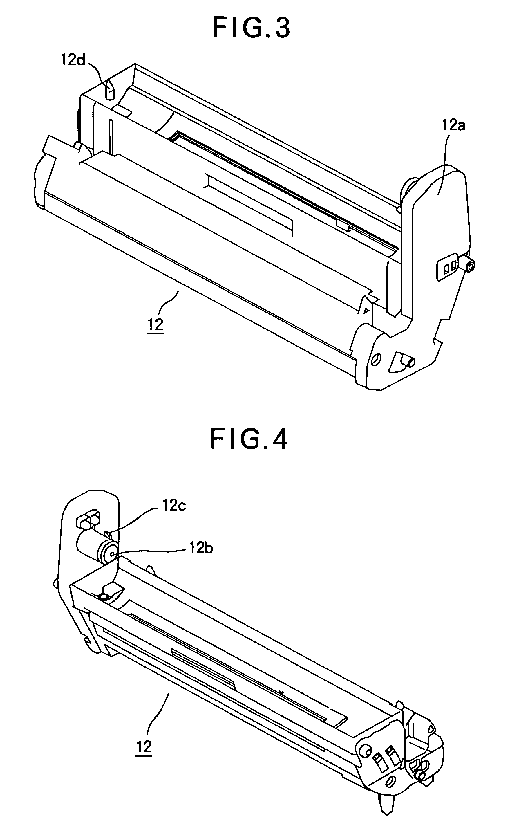
[0035]FIGS. 1 and 2 are perspective views of a toner cartridge 13 according to a first embodiment of the present invention. The toner cartridge 13 is attached to a process cartridge 12. The toner cartridge 13 has a fresh toner chamber 4 from which fresh, unused toner is supplied and a waste toner chamber 3 that accommodates waste toner therein. A lid 2 closes one end of the fresh toner chamber 4 and a lid 8 closes one end of the waste toner chamber 3. The lid 8 has an operating lever 5 for operating a shutter that opens and closes a toner-discharging opening 11. When the operating lever 5 is pivoted to an OPEN position, the shutter is opened so that the toner is discharged through the toner-discharging opening 11 by gravity in a direction shown by arrow A. When the operating lever 5 is pivoted to a CLOSED position, the shutter is be closed. The lid 2 has a waste toner-receiving opening 2h through which the waste toner is received. The lid 2 also has a recess 2g formed near the waste...

second embodiment

[0054]FIGS. 13-15 illustrate a toner cartridge 13 according to a second embodiment, showing details of a fitting construction that extends all around the peripheral portions of the openings of the housing 1 and the lid 2. A loop-like groove 1d is formed in the outer peripheral surface of the housing 1 near the opening, extending all around the outer peripheral surface. A loop-like projection 2f is formed on an inner surface of an outer wall 2b of the lid 2 to extend in a circumferential direction all around the perimeter of the inner surface. Just as in the first embodiment, an inner wall 2a of the lid 2 has a chamfered portion 2e at the outer corner of the inner wall 2a, the chamfered portion 2e extending in a circumferential direction all around the perimeter of the inner wall 2a.

[0055] There is a relation such that L5>L4>L3, where L5 is the height of the outer peripheral wall 1a, L4 is the height of a loop-like projection 2f, and L3 is the height of inner wall 2a. A chamfered po...

third embodiment

[0057]FIGS. 16-18 illustrate the configuration of a fitting construction according to a third embodiment. There are provided two grooves 2d that are formed in the outer peripheral surface of an inner wall 2a of a lid 2 and extend all around the outer peripheral surface of the inner wall 2a. There is a relation such that L6>L7, where L6 denotes the height of an inner wall 2a and L7 denotes the height of an outer wall 2b. The grooves 2d are above the outer wall 2b and therefore they are exposed and are visible. The grooves 2d have a depth smaller than half the thickness of the inner wall 2a. The loop-like projection 1b extends all around the outer peripheral wall 1a of the housing 1 and is a predetermined distance away from the opening.

[0058] The lid 2 is formed of a material having a smaller tensile modulus of elasticity than the housing 1 and the inner wall 2a has a chamfered portion 2e, so that the outer peripheral wall 1a of the housing 1 is allowed to fit over the inner wall 2a ...


PUM


Abstract

A fitting construction for a developer holding apparatus includes a housing member and a lid. The housing member has a developer chamber having a first wall that defines an opening. The lid fittingly closes the opening, the lid having a smaller tensile modulus of elasticity than the housing member and a groove that is formed in a peripheral portion of the lid and receives the projection therein. The groove extends all around the opening. The first wall fittingly engages into the groove to seal the opening. The lid includes a second wall that closes the opening, an third wall that projects from the second wall, and an fourth wall that projects from the second wall and extends to surround the third wall to define the groove between the third wall and the fourth wall.

Description

FIELD OF THE INVENTION [0001] The present invention relates to a fitting construction for use in an electrophotographic image-forming apparatus such as a printer, a facsimile machine, and a copying machine. DESCRIPTION OF THE RELATED ART [0002] Conventional electrophotographic image-forming apparatus use an electrophotographic image-forming process including exposing, developing, transferring, and fixing. A charging roller charges the surface of a photoconductive drum to a predetermined potential. An exposing unit irradiates the charged surface of the photoconductive drum with light in accordance with print data to form an electrostatic latent image. A developing roller applies developer to the electrostatic latent image to develop the electrostatic latent image into a visible image. A transfer roller transfers the visible image onto a recording medium. The visible image on the recording medium is then fixed in a fixing unit. The image-forming apparatus includes a developer-holding ...

Claims


Application Information

Patent Timeline
Patent Type & Authority Applications(United States)
IPC IPC(8): B65D41/46B65D83/06G03G15/08
CPCG03G2221/1648G03G2221/1651G03G15/0868G03G15/0886G03G15/0875
Inventor ODA, YUKIYOSHI
Owner OKI ELECTRIC IND CO LTD
Why Eureka
Try Eureka