
Method for frequency conversion and receiver

a frequency conversion and receiver technology, applied in the direction of radio transmission, oscillation generator, transmission, etc., can solve the problems of complicated preparation of a signal for the mixer, and the signal that has a dc component is not suitable for operation of the mixer

Active Publication Date: 2005-08-04
ATMEL CORP
View PDF5 Cites 4 Cited by
  • Summary
  • Abstract
  • Description
  • Claims
  • Application Information

AI Technical Summary

Benefits of technology

[0009] It is therefore an object of the present invention to provide a method for preparing a divided signal that stands in a fractional rational ratio to the undivided signal and that is suitable for a mixer without complicated further processing.

Problems solved by technology

However, a signal that has a DC component is not suitable for operating a mixer.
In the prior art, the DC component must therefore be removed by filtering, which makes the preparation of a signal for the mixer complicated.

Method used


Image

  • Method for frequency conversion and receiver
  • Method for frequency conversion and receiver
  • Method for frequency conversion and receiver

Examples


Embodiment Construction

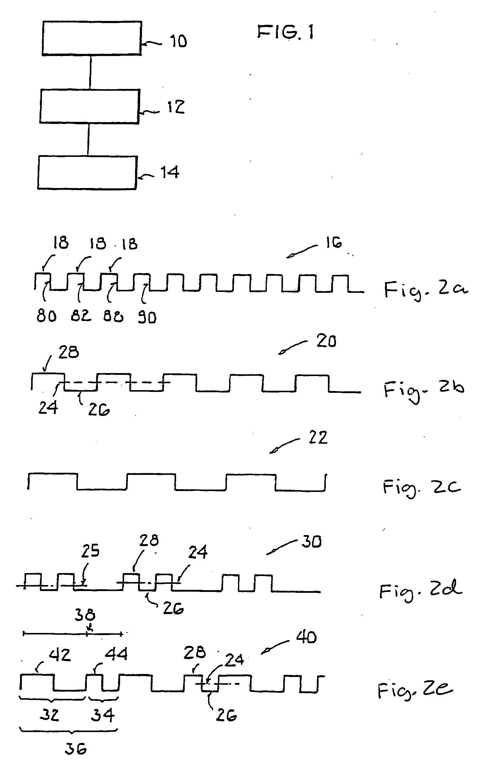
[0038]FIG. 1 shows a sequence of steps 10, 12, and 14, where an oscillator signal is produced in step 10, is divided in step 12, and is combined in step 14 with a first signal (receive signal) in a mixer.

[0039] In a first step 10, an oscillator signal f_O is continuously produced. Such an oscillator signal can, for example, be produced by a phase-locked loop with a voltage-controlled oscillator. The oscillator signal can, for example, be a square-wave signal with a symmetrical pulse duty ratio of 50% and thus has a periodic sequence 16 of square-wave pulses 18, as shown in FIG. 2a.

[0040] In step 12, a division of the output signal of the oscillator takes place. A division can, for example, be accomplished by generating, from the periodic sequence 16, a new square wave signal in which a signal level change is triggered by every nth edge (rising or falling) of the oscillator signal.

[0041] In this way, a halving of the oscillator frequency results when n=2. When n=3, the oscillator ...


PUM


Abstract

A method and device for frequency conversion is disclosed in which a first signal with a first frequency is converted into a second frequency through mixing with a divided oscillator signal and wherein the frequency of the divided oscillator signal stands in a fractional rational ratio to the frequency of the undivided oscillator signal. The method is characterized in that the oscillator signal is divided such that an average value of the divided oscillator signal over time corresponds to half the separation between the extreme values of the divided oscillator signal.

Description

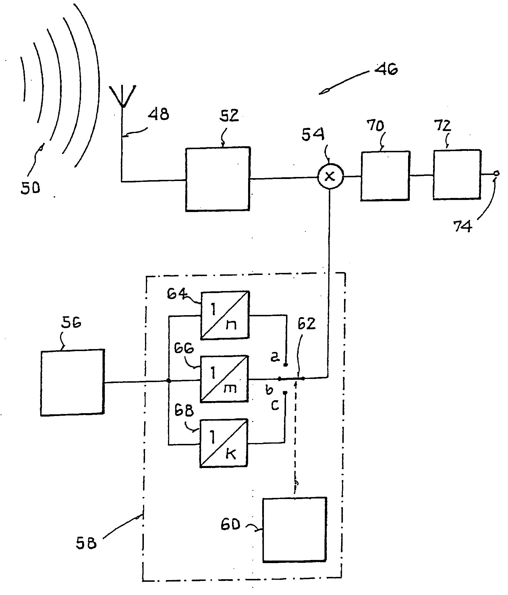
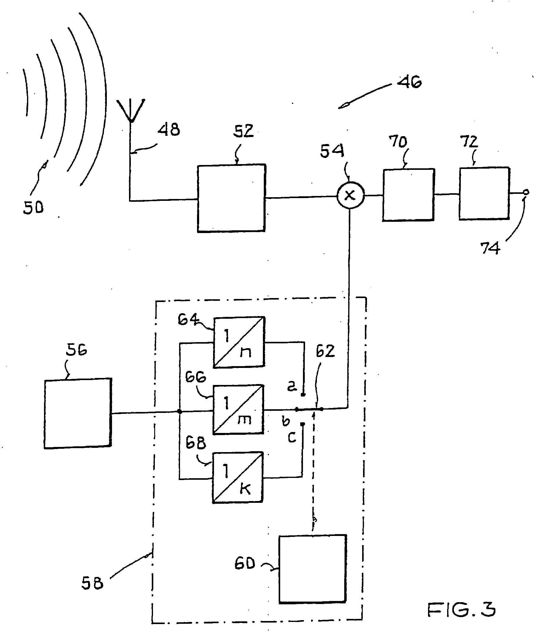
[0001] This nonprovisional application claims priority under 35 U.S.C. § 119(a) on German Patent Application No. DE 102004 005 503 filed in Germany on Jan. 30, 2004, which is herein incorporated by reference. BACKGROUND OF THE INVENTION [0002] 1. Field of the Invention [0003] The present invention relates to a method for frequency conversion in which a first signal with a first frequency is converted into a second frequency through mixing with a divided oscillator signal and wherein the frequency of the divided oscillator signal stands in a fractional rational ratio to the frequency of the undivided oscillator signal. [0004] In addition, the present invention relates to a receiver, having at least a mixer, an oscillator, and a switchable frequency divider for dividing a frequency of the oscillator by various natural numbers n, m, wherein the mixer mixes a first signal that has a first frequency with a divided signal from the oscillator and thus converts it to a second frequency, and...

Claims


Application Information

Patent Timeline
IPC IPC(8): H03B21/00H03D7/00H04B1/16H04B1/26H04B1/28H04B15/00
CPCH04B1/28
Inventor REBEL, REIMUND
Owner ATMEL CORP
Learn More