Method for frequency conversion and receiver
a frequency conversion and receiver technology, applied in the direction of radio transmission, oscillation generator, transmission, etc., can solve the problems of complicated preparation of a signal for the mixer, and the signal that has a dc component is not suitable for operation of the mixer
- Summary
- Abstract
- Description
- Claims
- Application Information
AI Technical Summary
Benefits of technology
Problems solved by technology
Method used
Image
Examples
Embodiment Construction
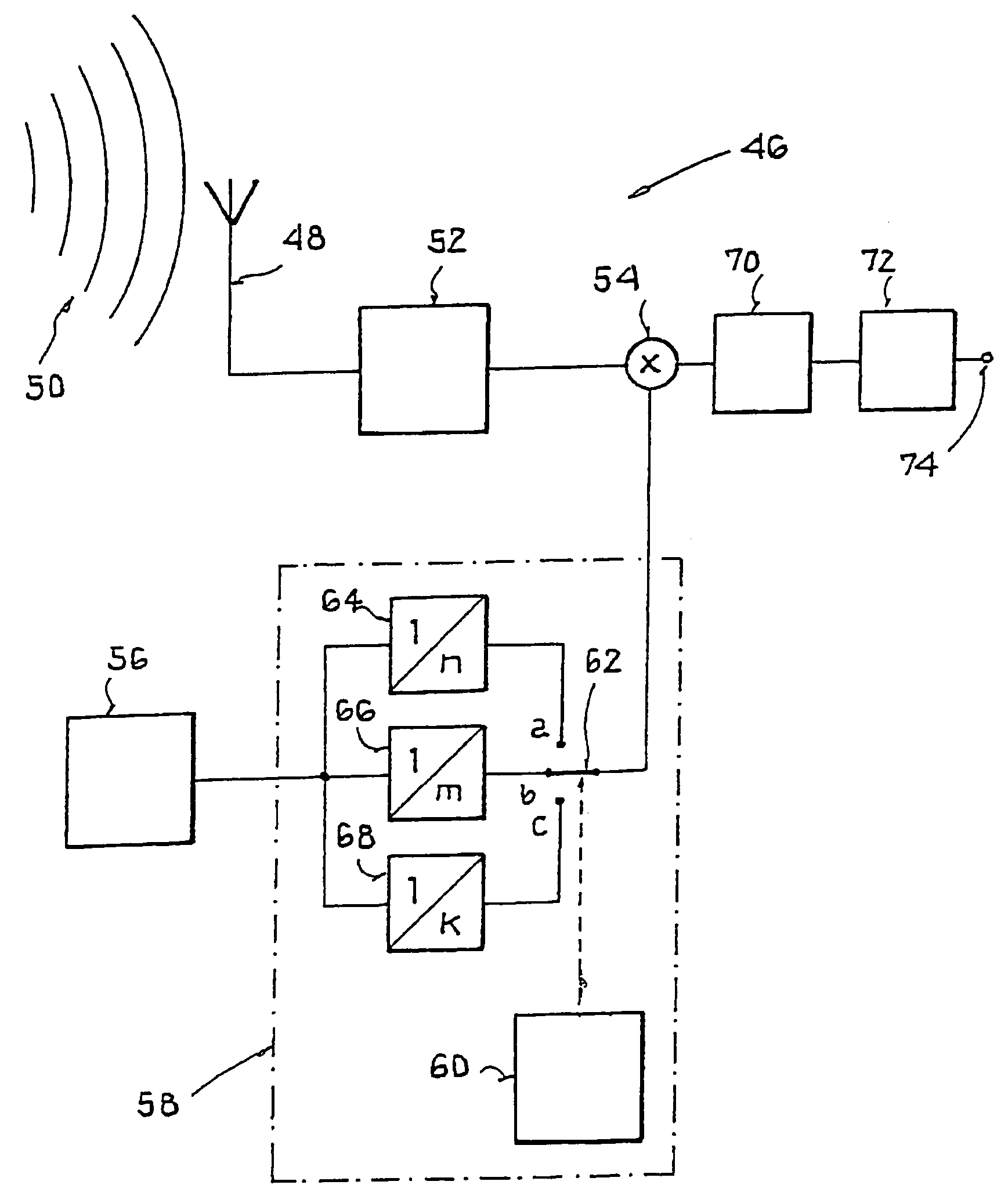
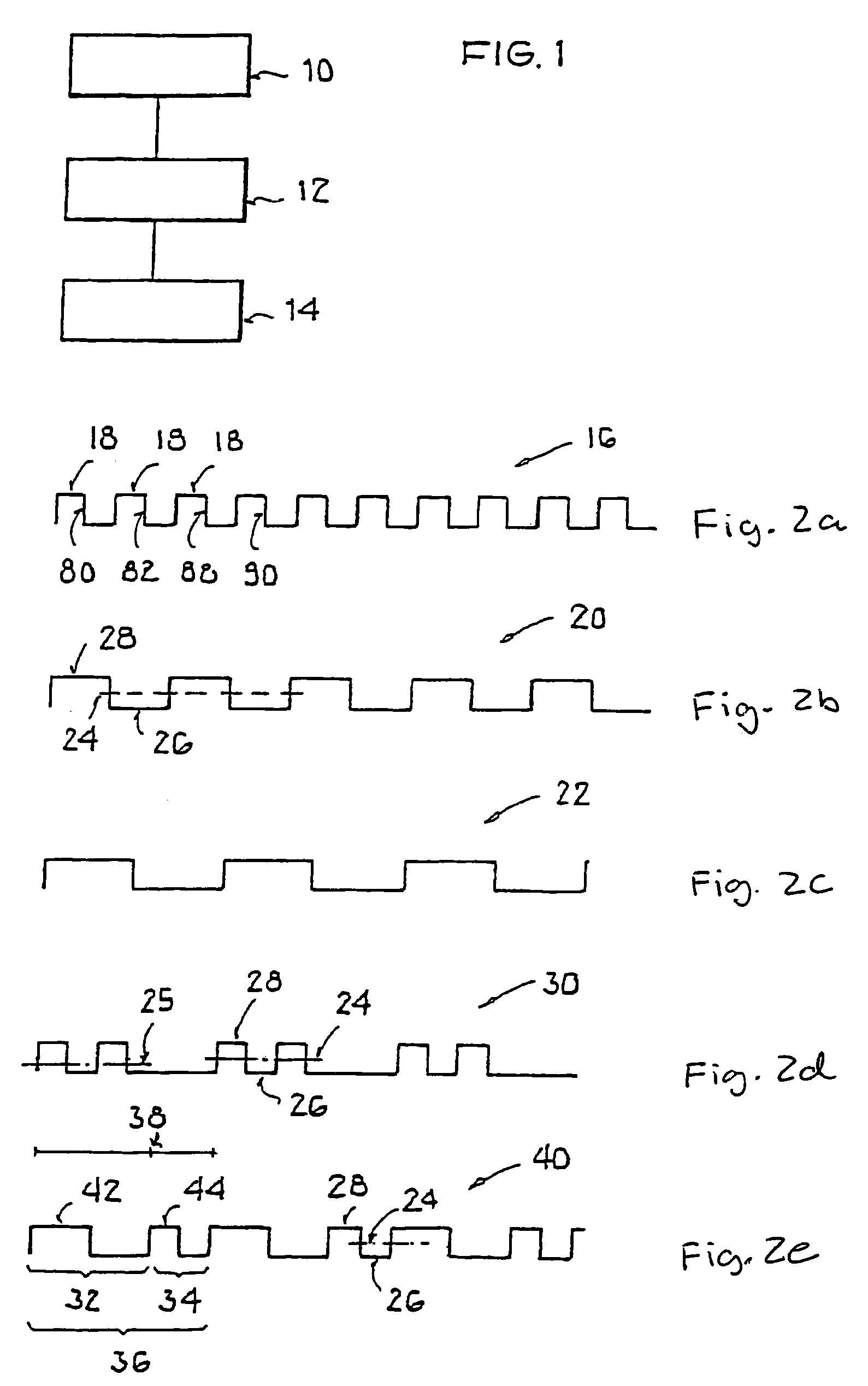
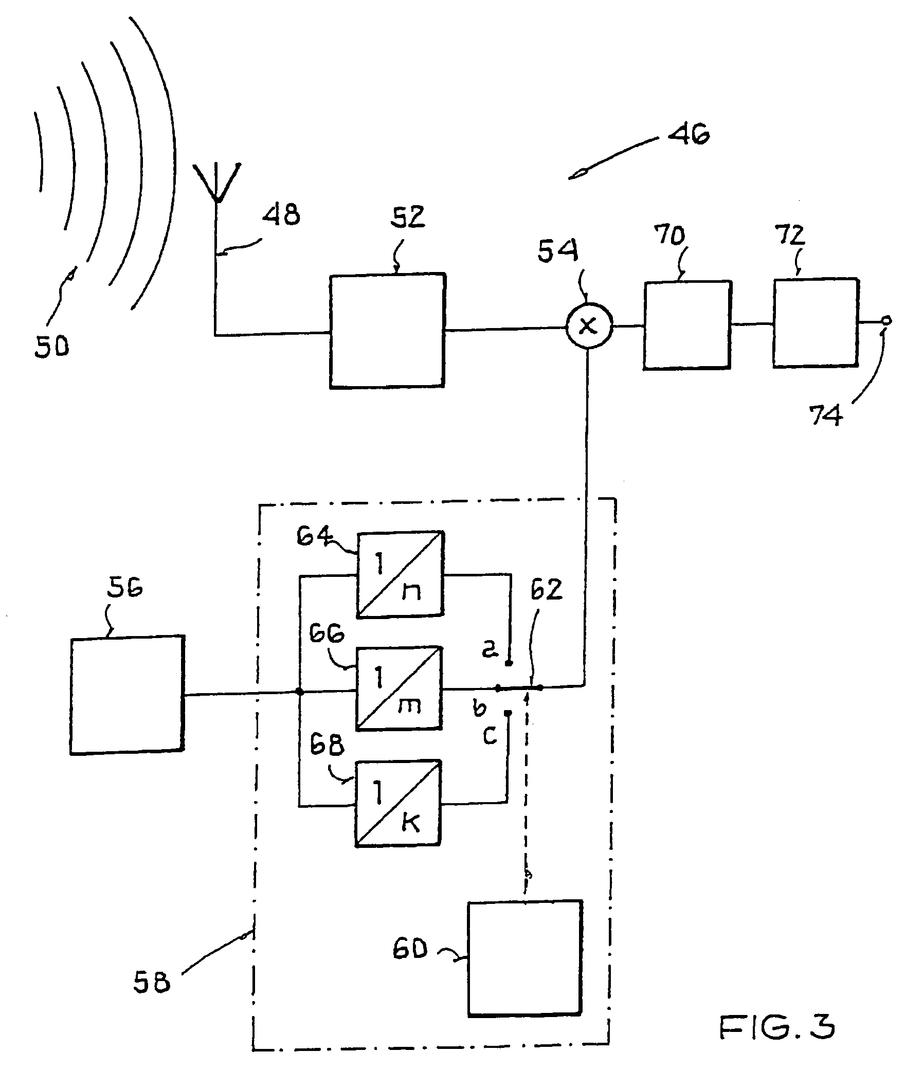
[0038]FIG. 1 shows a sequence of steps 10, 12, and 14, where an oscillator signal is produced in step 10, is divided in step 12, and is combined in step 14 with a first signal (receive signal) in a mixer.
[0039]In a first step 10, an oscillator signal f_O is continuously produced. Such an oscillator signal can, for example, be produced by a phase-locked loop with a voltage-controlled oscillator. The oscillator signal can, for example, be a square-wave signal with a symmetrical pulse duty ratio of 50% and thus has a periodic sequence 16 of square-wave pulses 18, as shown in FIG. 2a.
[0040]In step 12, a division of the output signal of the oscillator takes place. A division can, for example, be accomplished by generating, from the periodic sequence 16, a new square wave signal in which a signal level change is triggered by every nth edge (rising or falling) of the oscillator signal.
[0041]In this way, a halving of the oscillator frequency results when n=2. When n=3, the oscillator frequ...
PUM
 Abstract
Description
Claims
Application Information
 - R&D
- Intellectual Property
- Life Sciences
- Materials
- Tech Scout
- Unparalleled Data Quality
- Higher Quality Content
- 60% Fewer Hallucinations
Browse by: Latest US Patents, China's latest patents, Technical Efficacy Thesaurus, Application Domain, Technology Topic, Popular Technical Reports.
© 2025 PatSnap. All rights reserved.Legal|Privacy policy|Modern Slavery Act Transparency Statement|Sitemap|About US| Contact US: help@patsnap.com


