
Reading apparatus and non-transitory storage medium storing instructions executable by reading apparatus

Active Publication Date: 2015-04-30
BROTHER KOGYO KK
View PDF7 Cites 0 Cited by
  • Summary
  • Abstract
  • Description
  • Claims
  • Application Information

AI Technical Summary

Benefits of technology

The patent is for a reading apparatus and a non-transitory storage medium that contains instructions that can be executed by a processor of the reading apparatus. These instructions are designed to perform image processing for different regions of an image without causing complicated processing. The technical effect of this invention is to provide a more efficient and efficient way to process images.

Problems solved by technology

However, it is difficult to identify the facial region and the character region on the image, so that recognition processing may be complicated, and in worse case the recognition may fail, making it impossible to execute an appropriate processing on each region.

Method used


Image

  • Reading apparatus and non-transitory storage medium storing instructions executable by reading apparatus
  • Reading apparatus and non-transitory storage medium storing instructions executable by reading apparatus
  • Reading apparatus and non-transitory storage medium storing instructions executable by reading apparatus

Examples


first embodiment

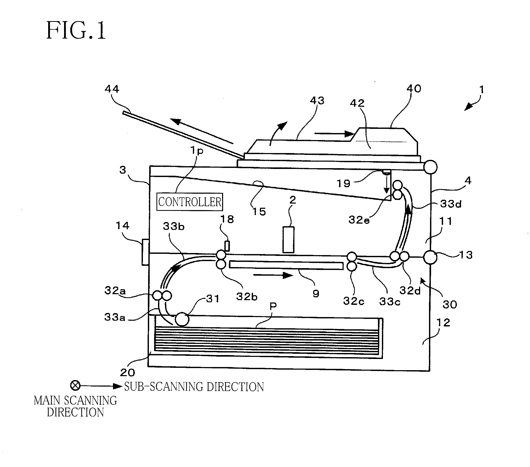
[0024]Hereinafter, there will be described an image recording apparatus according to a first embodiment of the present invention by reference to the drawings. In the present embodiment, the present invention is applied to a multi-function peripheral (MFP) having a scanning function and a printing function.

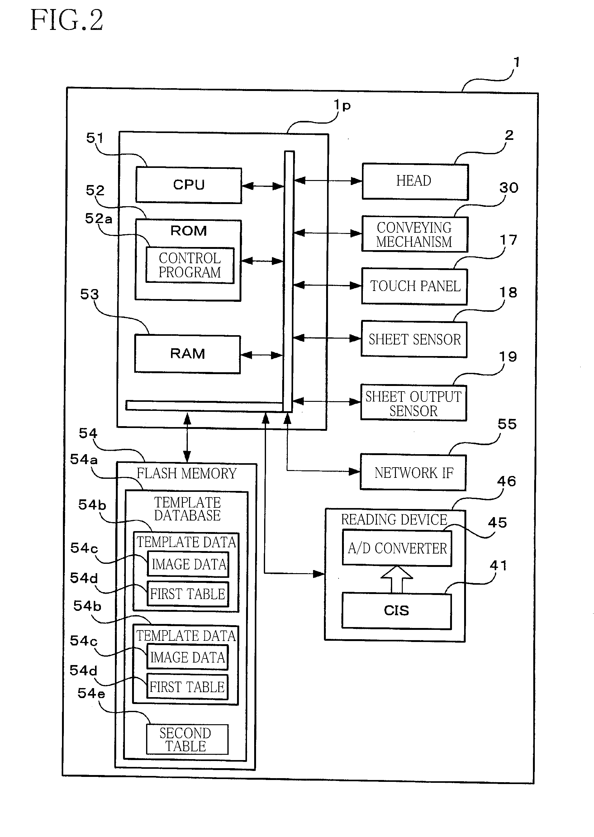
[0025]As illustrated in FIG. 1, an MFP 1 includes an upper housing 11 and a lower housing 12 each having a rectangular parallelepiped shape. The MFP 1 has a front surface 3 (a left surface in FIG. 1) and a rear surface 4 (a right surface in FIG. 1). The upper housing 11 is open in its lower side, and the lower housing 12 is open in its upper side. The upper housing 11 is coupled to the lower housing 12 so as to be pivotable about a pivot shaft 13 with respect to the lower housing 12. An upper surface of the upper housing 11 includes a sheet support portion 15. Sheets P printed and discharged are sequentially placed onto the sheet support portion 15. A sheet output sensor 19 is disp...

second embodiment

[0047]There will be next explained a second embodiment with reference to FIGS. 7-9. It is noted that the same numerals as used in the first embodiment are used to designate the corresponding elements and steps of this second embodiment, and an explanation of which is dispensed with. In the present embodiment, the template database stored in the flash memory 54 contains only the second table 54e and does not contain the template data 54b. As illustrated in FIG. 7, the CPU 51 can print a card 270 such that two dimensional codes 72a-72e each as one example of an identification mark are arranged near the respective input fields 71a-71e. Each of the two-dimensional codes 72a-72e indicates the location information and the attribute (as one example of an image processing indicator in the present embodiment) of a corresponding one of the input fields 71a-71e. It is noted that the two-dimensional codes 72a-72e may be arranged at any locations as long as the location information is not indica...


PUM


Abstract

A reading apparatus includes a reading device for reading an image on a recording medium and generating image data. The reading apparatus is configured to: receive the generated image data; retrieve a first region location indicator indicating a location of a first region to be defined on an image based on the generated image data, a second region location indicator indicating a location of a second region, a first image processing indicator indicating at least one image processing determined for the first region, and a second image processing indicator indicating at least one image processing determined for the second region; determine first partial image data based on the first region location indicator; execute the at least one image processing; determine second partial image data; and execute the at least one image processing.

Description

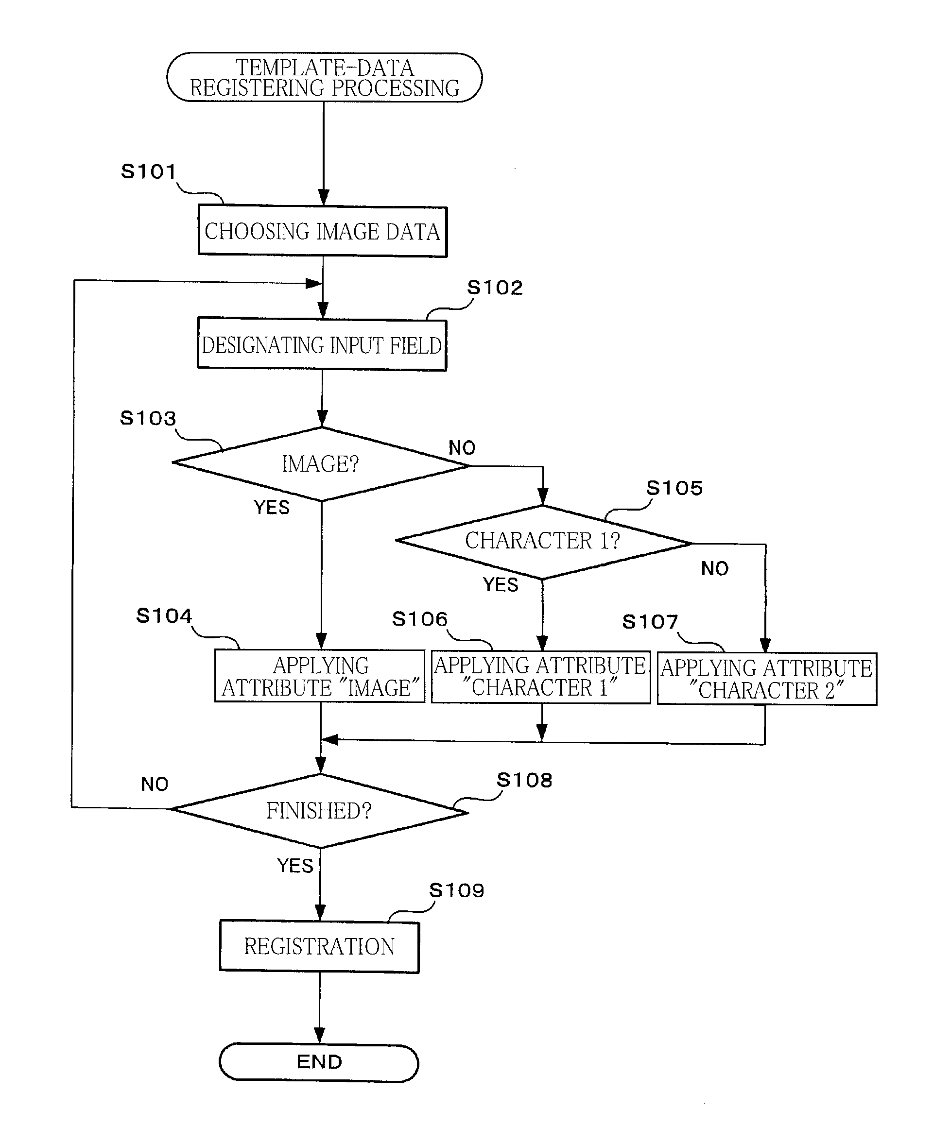
CROSS REFERENCE TO RELATED APPLICATION[0001]The present application claims priority from Japanese Patent Application No. 2013-226791, which was filed on Oct. 31, 2013, the disclosure of which is herein incorporated by reference in its entirety.BACKGROUND[0002]1. Technical Field[0003]The present invention relates to a reading apparatus configured to read an image and to a non-transitory storage medium storing a plurality of instructions executable by a processor of the reading apparatus.[0004]2. Description of the Related Art[0005]There have been known techniques of facial recognition and character recognition (such as optical character recognition or OCR) for a scanned image.SUMMARY[0006]A facial region and a character region on an image need to be identified for the facial recognition or the OCR. However, it is difficult to identify the facial region and the character region on the image, so that recognition processing may be complicated, and in worse case the recognition may fail,...

Claims


Application Information

Patent Timeline
IPC IPC(8): H04N1/40H04N1/407H04N1/21H04N1/00
CPCH04N1/40062H04N1/00013H04N2201/0081H04N1/21H04N2201/0094H04N1/4072
Inventor XU, SHAN
Owner BROTHER KOGYO KK
Learn More