
Optical disc type determining method and optical disc device

a technology of optical discs and types, applied in the direction of digital signal error detection/correction, instruments, recording signal processing, etc., can solve the problems of not being able to perform normal playback in a cd standard setting, not being able to identify or erroneously recognize the cd signal surface b>42/b> of the dual disc b>40, and achieving the effect of reliably determining a plurality of types

Active Publication Date: 2010-09-21
JVC KENWOOD CORP
View PDF6 Cites 2 Cited by
  • Summary
  • Abstract
  • Description
  • Claims
  • Application Information

AI Technical Summary

Benefits of technology

[0016]Therefore, there is a desire for an optical disc type determining method and an optical disc device capable of reliably determining a CD signal surface of a double-sided dual disc and also reliably determining a plurality of types of optical discs without any new unit or without complicated processing.
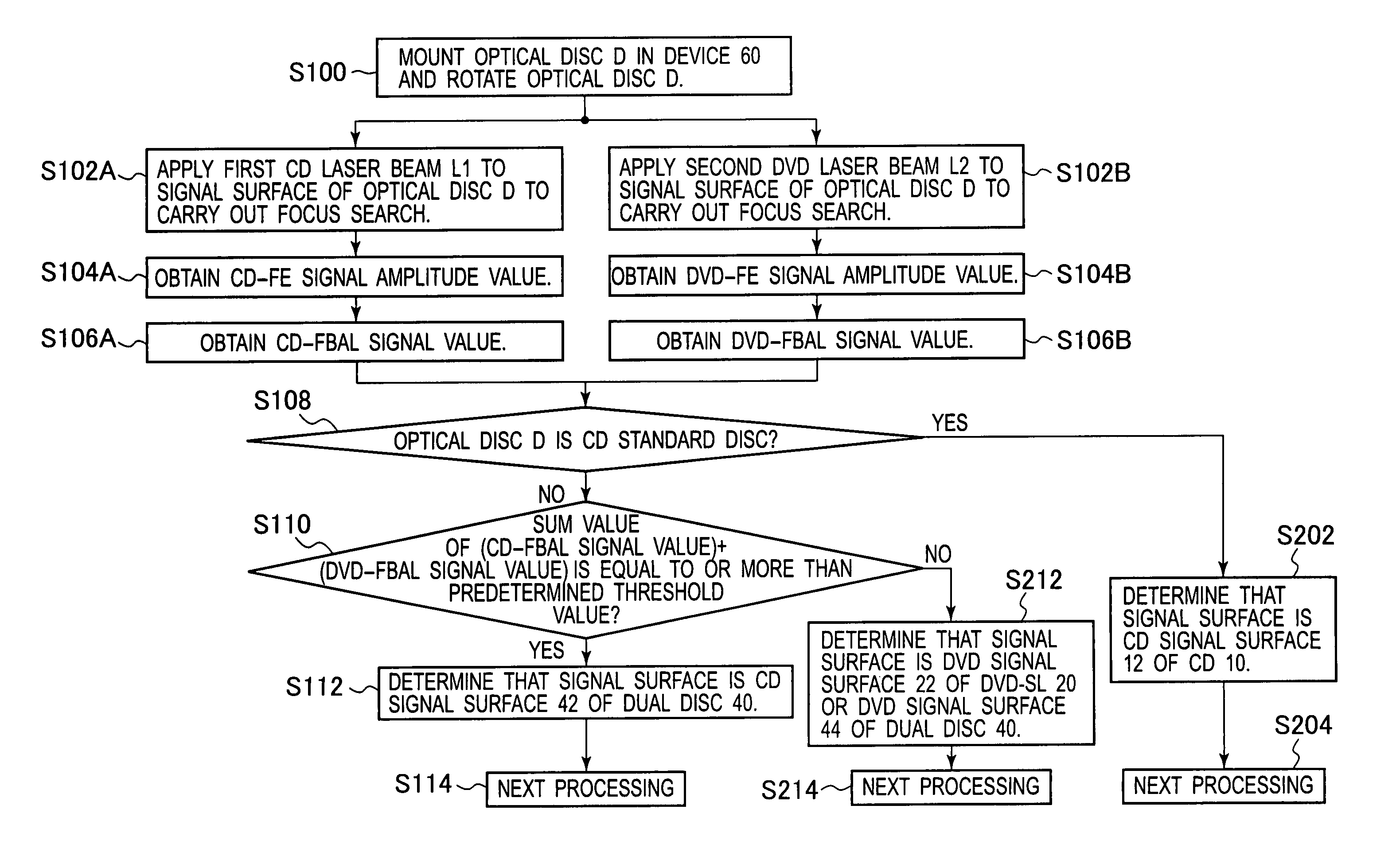
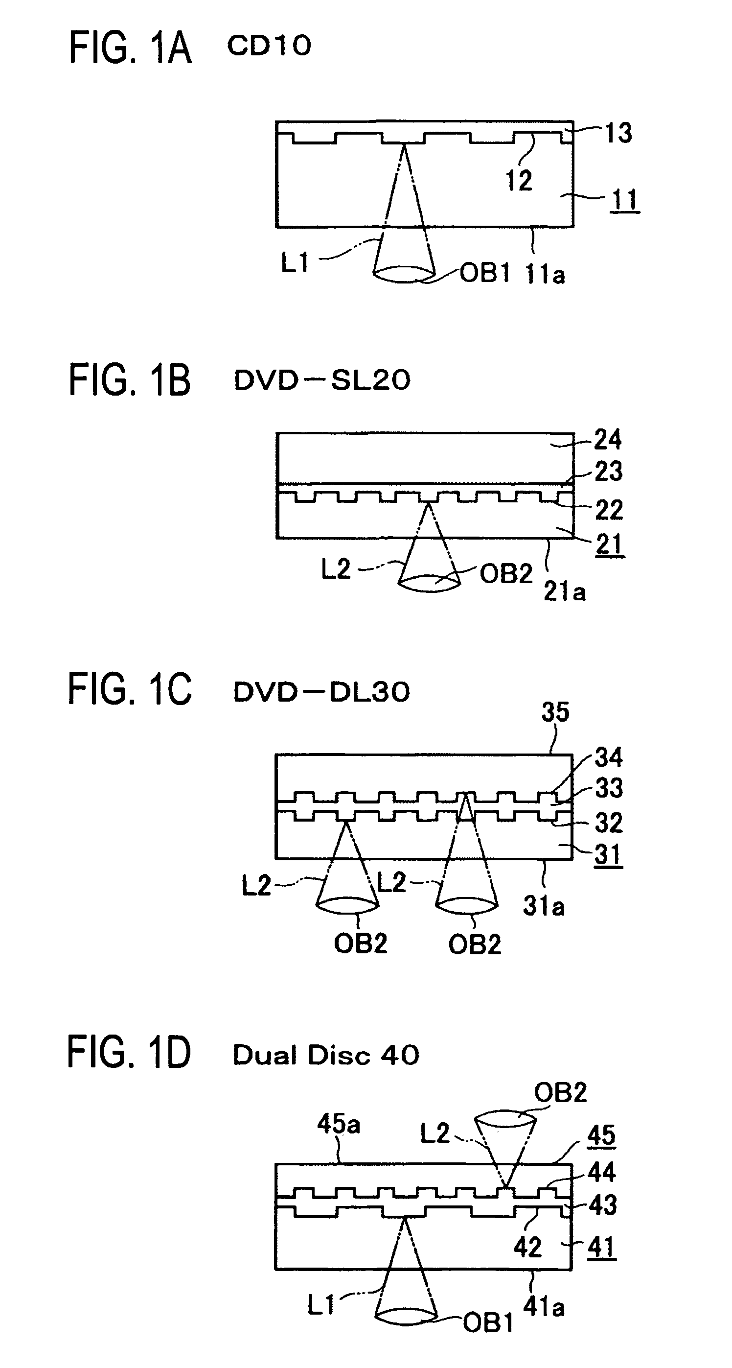
[0047]According to the optical disc type determining method of (1), (2) and the optical disc device of (4), (5), a mounted optical disc is determined to be any one of the following types of selectively mountable optical discs: a first optical disc which has a first signal surface compliant with a first recording format located a first distance away from a beam entrance surface of a first-optical disc substrate, a first laser beam being applied to the first signal surface to record or reproduce an information signal; a second optical disc which has a second signal surface compliant with a second recording format located a second distance away from a beam entrance surface of a second optical disc substrate, the value of the second distance being smaller than that of the first distance, a second laser beam at a wavelength shorter than that of the first laser beam being applied to the second signal surface to record or reproduce an information signal; and a third optical disc which has a third signal surface compliant with the first recording format located a third distance away from a beam entrance surface of a third optical disc substrate, the value of the third distance being between those of the first distance and the second distance, the first laser beam being applied to the third signal surface to record or reproduce an information signal. At this point, in particular, whether the optical disc is the first optical disc is determined with reference to at least one of first and second focus error signal amplitude values. Then, in the case where the optical disc is determined not to be the first optical disc, the optical disc is determined to be the third optical disc when a sum value of the addition of a first focus balance signal value to a second focus balance signal value is equal to or more than a predetermined threshold value, while the optical disc is determined to be the second optical disc when the sum value is smaller than the predetermined threshold value. Thus, it is possible to accurately determine the first to third optical discs of the three types, and it is also possible to provide an optical disc device at low cost because there is no need for a new unit or complicated processing in the optical disc device to determine the type of optical disc.
[0049]Furthermore, according to the optical disc type determining method of (3) and the optical disc device of (6), a mounted optical disc is determined to be any one of the following types of selectively mountable optical discs: a first optical disc which has a first signal surface compliant with a first recording format located a first distance away from a beam entrance surface of a first optical disc substrate, a first laser beam being applied to the first signal surface to record or reproduce an information signal; and a second optical disc which has a second signal surface compliant with a second recording format located a second distance away from a beam entrance surface of a second optical disc substrate, the value of the second distance being smaller than that of the first distance, a second laser beam at a wavelength shorter than that of the first laser beam being applied to the second signal surface to record or reproduce an information signal. At this point, in particular, whether the optical disc is determined to be the first optical disc when a sum value of the addition of a first focus balance signal value to a second focus balance signal value is equal to or more than a predetermined threshold value, while the optical disc is determined to be the second optical disc when the sum value is smaller than the predetermined threshold value. Thus, the determining operation is simpler than in the optical disc type determining method of (1), (2) and the optical disc device of (4), (5) described above, so that it is possible to accurately and speedily determine the first and second optical discs of the two types.

Problems solved by technology

Therefore, even if the technical idea of the disc determining method disclosed in Japanese Patent Publication Laid-open No. 11-066712 is applied, there arises a problem that the CD signal surface 42 of the dual disc 40 can not be identified or erroneously recognized.
Moreover, as the position from the beam entrance surface is difference between the CD signal surface 42 of the dual disc 40 and the CD signal surface 12 of the CD 10, there is a problem that normal playback can not be carried out in a CD standard setting and that much time is required for the adjustment of a focal position.

Method used


Image

  • Optical disc type determining method and optical disc device
  • Optical disc type determining method and optical disc device
  • Optical disc type determining method and optical disc device

Examples


Embodiment Construction

[0061]One embodiment of an optical disc type determining method and an optical disc device according to the present invention will hereinafter be described in detail with reference to FIG. 2 to FIG. 9. It is to be noted that the same numbers are assigned in the following description to the same members as those previously described with FIGS. 1A to 1D.

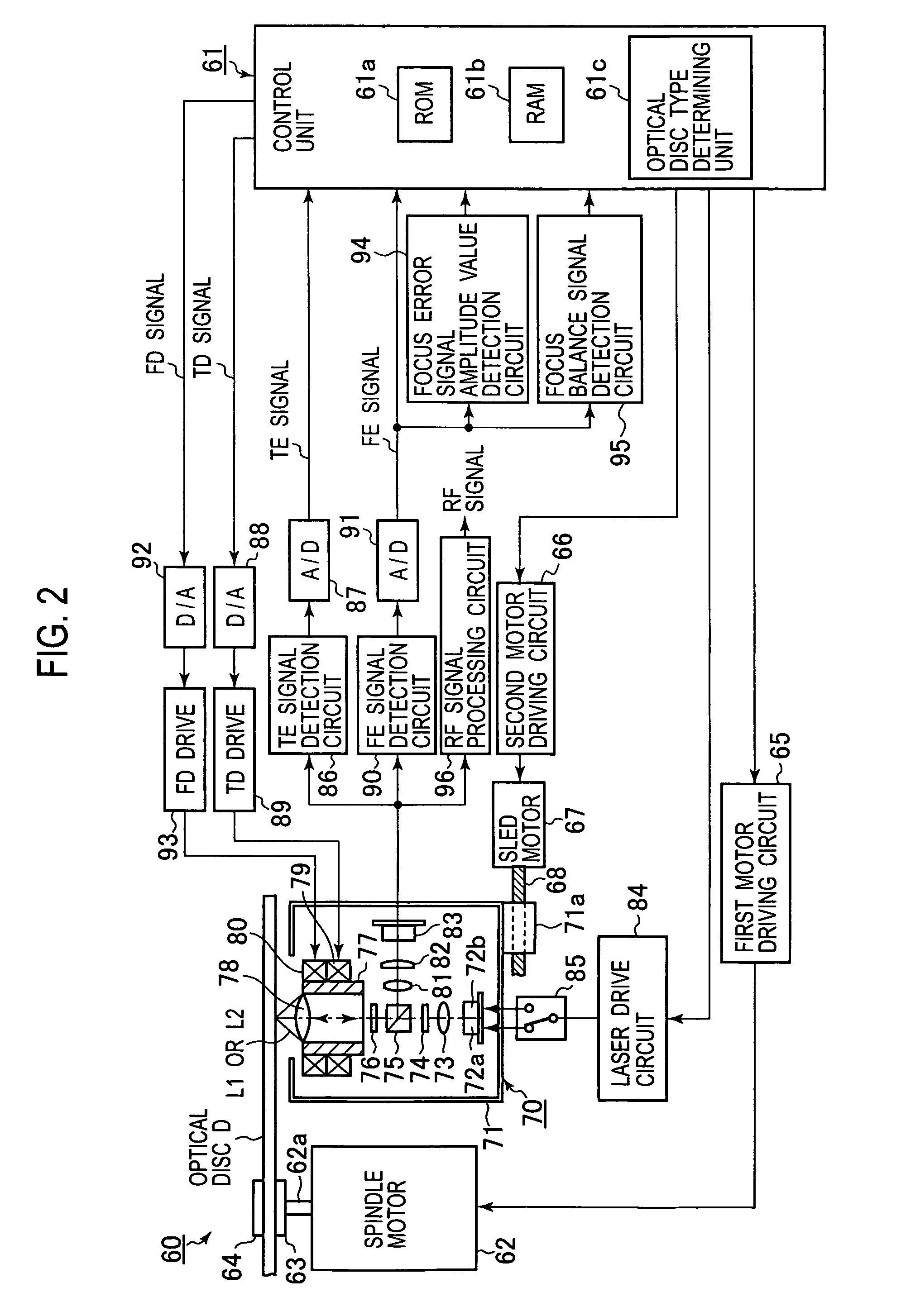
[0062]FIG. 2 is a diagram showing the whole configuration of an optical disc device according to the present invention. FIG. 3 is a diagram showing, in an enlarged form, a multi-divided photodetector provided in an optical pickup. FIG. 4 is a diagram schematically showing a focus error signal to find a focus error signal amplitude value and a focus balance signal value which serve as the essential parts of the present invention.

[0063]As shown in FIG. 2, in an optical disc device 60 in the embodiment, there is provided a control unit 61 for controlling the entire device using a microcomputer. In the control unit 61, there are provided a...


PUM


Abstract

Whether an optical disc is a first optical disc or not is determined with reference to at least one of first and second focus error signal amplitude values. Then, if a sum value of the addition of a first focus balance signal value (CD-FBAL signal value) to a second focus balance signal value (DVD-FBAL signal value) is equal to or more than a predetermined threshold value, the signal surface of the optical disc is determined to be a CD signal surface of a dual disc. On the other hand, if the sum value is smaller than the predetermined threshold value, the signal surface of the optical disc is determined to be a DVD signal surface of a DVD or a DVD signal surface of a dual disc.

Description

BACKGROUND OF THE INVENTION[0001]1. Field of the Invention[0002]The present invention relates to an optical disc type determining method and an optical disc device, capable of reliably determining a CD signal surface of a double-sided dual disc which has, on one side, a DVD signal surface for recording data compliant with a DVD standard and, on the other side, the CD signal surface for recording data compliant with a signal standard equivalent to a CD standard, and also capable of reliably determining a plurality of types of optical discs.[0003]2. Description of the Related Art[0004]Generally, in circular-plate-shaped optical discs, information signals such as music data, image data or computer data are highly densely recorded in a track spirally (or concentrically) formed on a signal surface of a substrate of the optical disc, and a desired track can be accessed at high velocity when a recorded track is played back, such that the optical discs are used in various ways.[0005]The opt...

Claims


Application Information

Patent Timeline
Patent Type & Authority Patents(United States)
IPC IPC(8): G11B5/58
CPCG11B19/12
Inventor KAWAGUCHI, MASHIRO
Owner JVC KENWOOD CORP
Learn More