
Batting system

Inactive Publication Date: 2005-08-04
HOLLROCK J RICHARD
View PDF21 Cites 3 Cited by
  • Summary
  • Abstract
  • Description
  • Claims
  • Application Information

AI Technical Summary

Problems solved by technology

As a result, the batter never realizes how far the baseball may have gone, or knows the ultimate trajectory resulting from his / her swing the batter may have used on the pitch.
In other batting systems, the pitching machine might be located in an open field into which a baseball may be hit, providing baseballs to the machine can then pose a problem.

Method used


Image

  • Batting system
  • Batting system
  • Batting system

Examples


Embodiment Construction

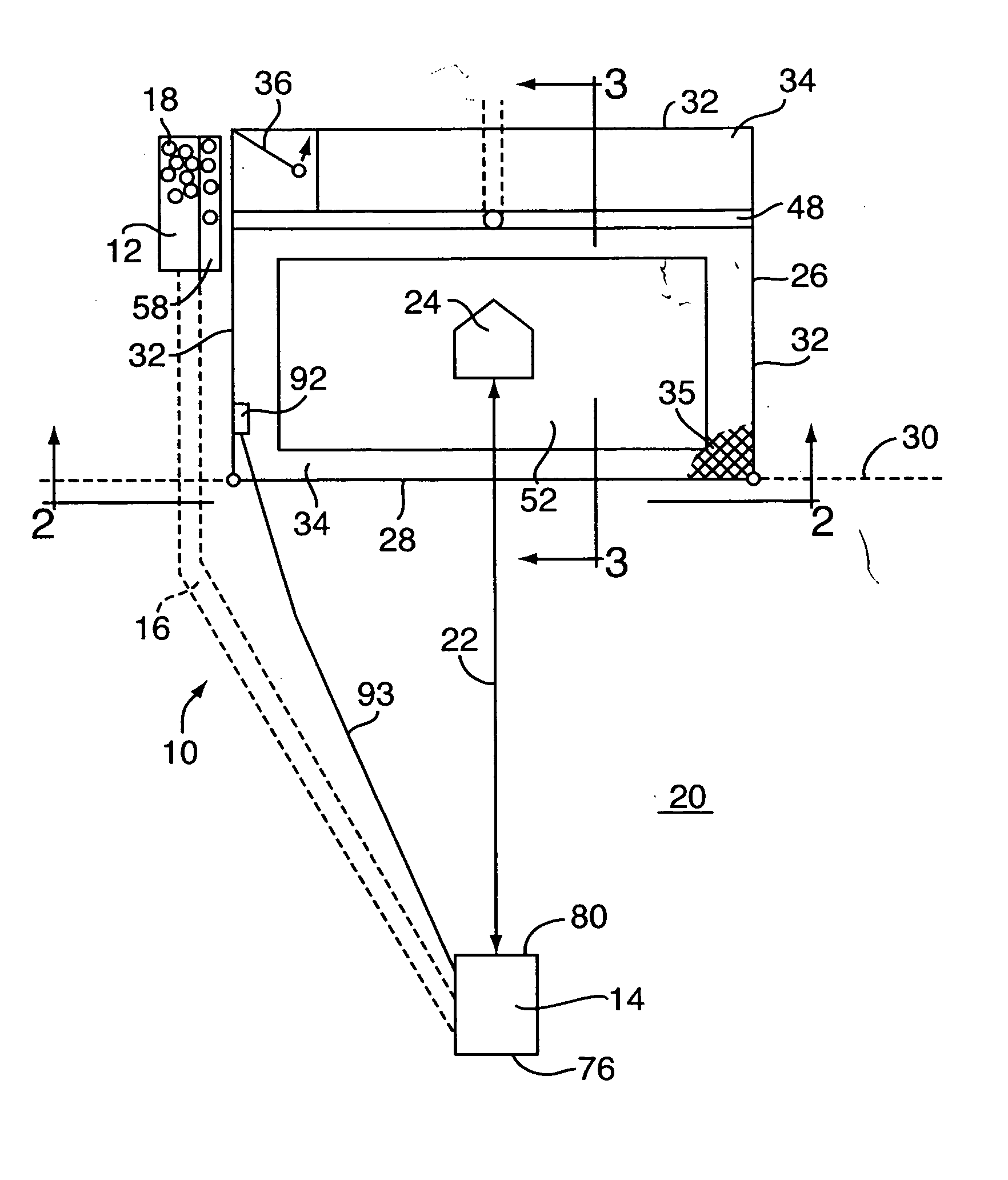
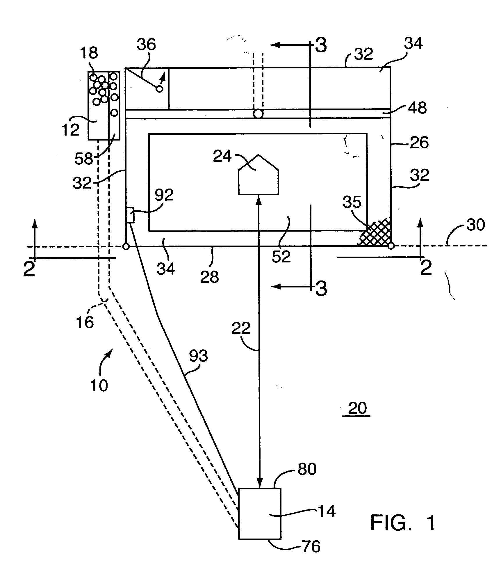
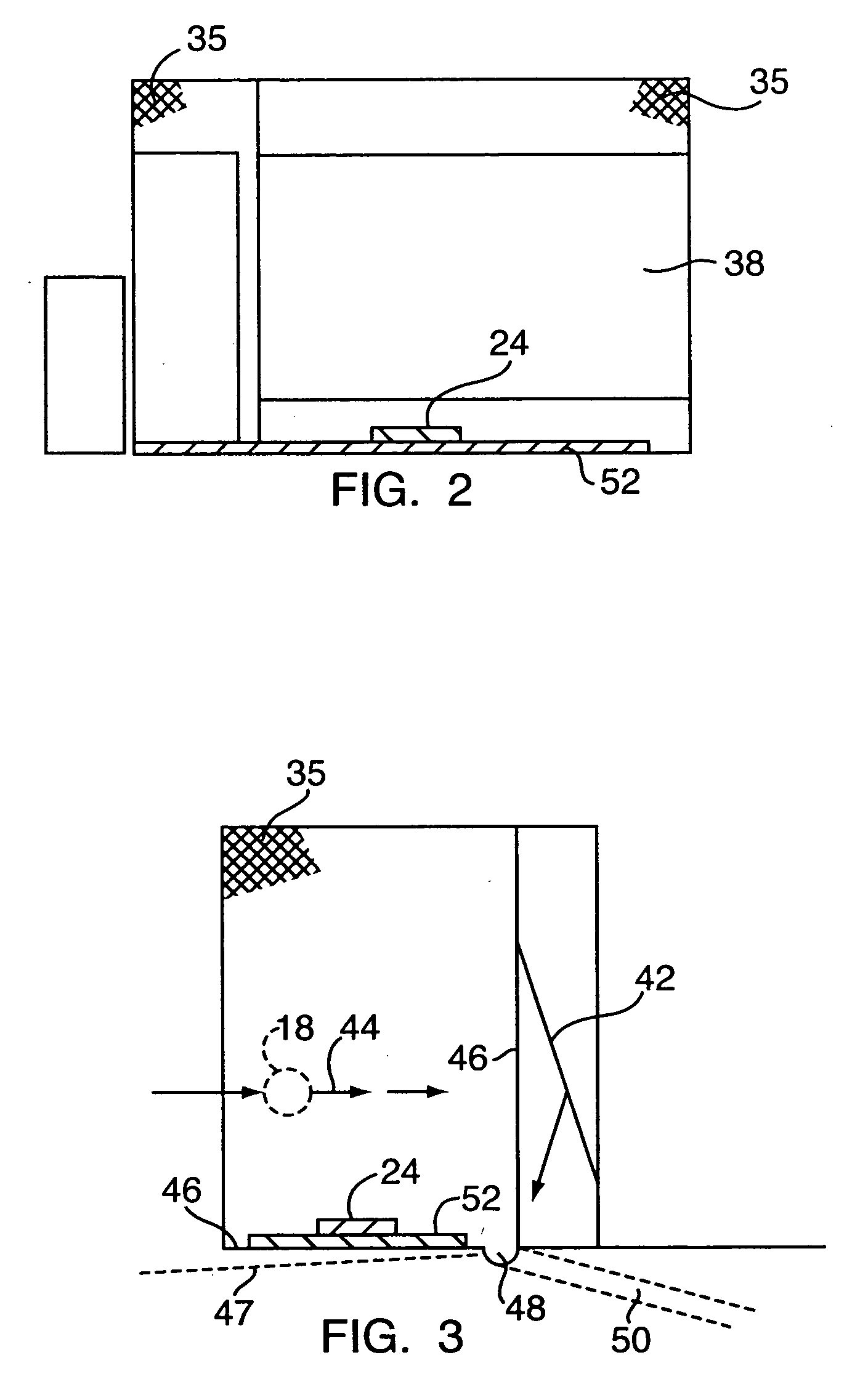
[0023] As shown in FIGS. 1-3, the batting system, generally denoted by the reference number 10 includes a baseball hopper 12, a pitching machine 14, and a baseball transport 16. The baseball transport 16 conducts baseballs 18 from the baseball hopper 12 to the pitching machine 14. When installed, the pitching machine 14 is positioned at a pitching position in a field 20 at a pitching distance 22 from a batting position designated by a plate 24. The pitching distance 22 is determined by the application based on such factors as the characteristics of the pitching machine 14, and the time needed by a batter (not shown) standing at the plate 24 to acquire visually and to react physically to a baseball 18 pitched by the pitching machine 14.

[0024] As stated above, the pitching machine 14 is positioned in the field 20. The field 20 is an area into which a baseball 18 properly struck by a bat (not shown) swung by the batter (not shown) will land. The plate 24 is located within a cage 26 ha...


PUM


Abstract

A batting system wherein the ball hopper is located proximate a batting position and a pitching machine is located at a pitching position with a ball transport system for conveying baseballs from the ball hopper to the pitching machine. The system provides for the continuous operation of the pitching machine without the need of an operator to approach the pitching machine. In addition, the batting system allows multiple batting systems to use continuously the same field as well as use a field also used as part of a golf driving range.

Description

CROSS-REFERENCE TO RELATED APPLICATIONS [0001] This application claims priority to U.S. Provisional Application 60 / 350,299 entitled “Open Loop Batting System,” filed Jan, 15, 2002, the entire disclosure of which is incorporated herein by reference.FIELD OF THE INVENTION[0002] The invention generally relates to recreational sporting equipment and more specifically to a batting system for practicing hitting a baseball. BACKGROUND OF THE INVENTION [0003] In prior art batting systems, a pitching machine pitches a baseball toward a batter who is supposed to hit the pitched baseball with his / her bat. The batter stands within an enclosure, or cage, and the baseball is pitched toward the batter by the pitching machine. Generally when the batter strikes the baseball, he / she has little feedback on the baseball trajectory because the baseball trajectory is restrained by the enclosure. The trajectory of the baseball is interrupted so that the batter cannot see where the baseball would normally ...

Claims


Application Information

Patent Timeline
IPC IPC(8): A63B43/00A63B47/02A63B69/00A63B69/36A63B69/40
CPCA63B43/00A63B47/025A63B2069/0008A63B69/3691A63B69/40A63B69/0002
Inventor HOLLROCK, J. RICHARD
Owner HOLLROCK J RICHARD
Learn More