State of charge range

a lithium-ion battery and state of charge technology, applied in the direction of battery/fuel cell control arrangement, charging stations, transportation and packaging, etc., can solve the problems of difficult to accurately ascertain battery capacity, serious repercussions, and technique that does not provide a very accurate assessment of battery capacity, so as to improve the cycle lifetime of lithium-ion battery packs and reduce the capacity of battery pack cells.

Active Publication Date: 2011-06-30
TESLA INC
View PDF3 Cites 40 Cited by
  • Summary
  • Abstract
  • Description
  • Claims
  • Application Information

AI Technical Summary

Benefits of technology

[0020]Disclosed is a system and method for improving cycle lifetimes for a lithium-ion battery pack, particularly for adapting to decreases in battery pack cell capacity as a function of age. A management system for a battery cell pack, the management system including a controller determining an adjustable charge profile for the battery cell pack wherein the adjustable charge profile includes an operational parameter identifying a next operation drive range mode from a set of drive range modes for the battery cell pack wherein each the drive range mode includes a state of charge (SOC) window between a charge SOC and a discharge SOC, with the set of drive range modes including a first drive range mode having a first SOC window and including a second drive range mode having a second SOC window less than the first SOC window; and one or more energy transfer stages to produce the charge SOC of the next operation drive range mode in the battery cell pack.

Problems solved by technology

Unfortunately, under normal use conditions such as those encountered in an electric vehicle or other battery-power device, it is difficult to accurately ascertain battery capacity.
Unfortunately this technique does not provide a very accurate assessment of battery capacity, both because some factors are not properly taken into account (e.g., historical temperature profiles, load conditions, depth of discharge prior to each charging, charge / discharge rates, and the like) and because the effects of the errors accumulate as the battery ages.
Although this technique can be used occasionally, using it on a routine basis can have serious repercussions since deep discharging a battery, and in particular fully discharging a battery, can dramatically shorten its lifetime.
Additionally, for most battery-powered devices, especially electric vehicles, it would be extremely inconvenient to require that the user allow the battery to become fully discharged prior to charging.
As battery packs used for heavy use, such as automotive electric vehicles and other heavy industrial application often have thousands of battery cells, and the assembly of the cells represents a large investment of resources (money and time), issues regarding safety and degradation are even more important.
This capacity loss manifests itself in increased internal resistance caused by mechanical stresses (e.g., volume change, side reactions and the like) and oxidation.
Eventually, the cell resistance reaches a point where the pack is unable to deliver the stored energy although the battery may still have ample charge.
High charge levels and elevated temperatures hasten permanent capacity loss.
High charge voltages, excessive charge rate and extreme load conditions will have a negative effect and shorten the battery life.
Not only is it better to charge lithium-ion battery at a slower charge rate, high discharge rates also contribute the extra wear and tear.
A moderate charge and discharge puts less stress on the battery, resulting in a longer cycle life.
Even though incremental improvements may be achieved with careful use of the battery, the battery cell environment and the services required are not always conducive to achieve optimal battery life.
The very considerations given above for increasing battery cycle life can often conflict with some of the requirements for long vehicle range and use of high performance battery packs used in automotive applications and other industrial scenarios.
The challenges are increased because each user will have different requirements, and those requirements will vary over time.
In short, there is typically not a single solution that can be established a priori for each user.
Use of newer technology and use of higher density can have an unintended result with the end-user, the owner of the electric vehicle.
As charging systems are conventionally implemented, it is the case that available charge from the higher energy density battery system will degrade faster with age than lower energy density battery systems.
The end-user who focuses on the change in capacity (i.e., range) over time may perceive that the newer battery technology is inferior or malfunctioning.
The interrelationships of SOC levels, charging, and use can be complex making appreciation of subtle differences challenging for some end-users.
And tuning the various parameters for any particular end-user can be challenging as well, particularly as different end-user operation patterns can significantly affect capacity degradation, particularly when charging and battery management is not complementary to the end-user operation.

Method used


Image

  • State of charge range
  • State of charge range
  • State of charge range

Examples


Embodiment Construction

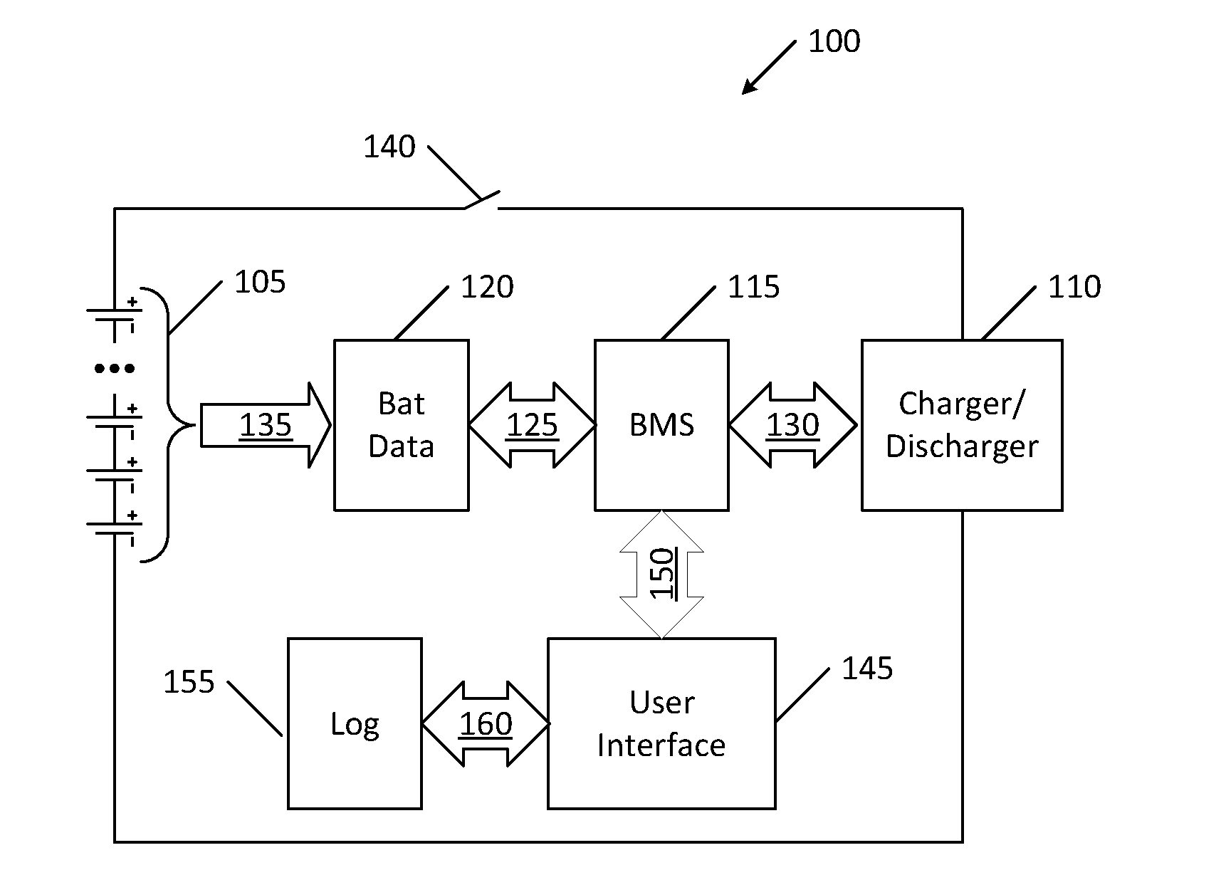
[0034]Embodiments of the present invention provide a system and method for a management system and a battery charger for improving cycle lifetimes for a battery cell pack, particularly for adapting to decreases in battery pack cell capacity as a function of age. The following description is presented to enable one of ordinary skill in the art to make and use the invention and is provided in the context of a patent application and its requirements. In the following text, the terms “battery”, “cell”, “battery cell” and “battery cell pack” may be used interchangeably and may refer to any of a variety of different rechargeable cell chemistries and configurations including, but not limited to, lithium ion (e.g., lithium iron phosphate, lithium cobalt oxide, other lithium metal oxides, etc.), lithium ion polymer, nickel metal hydride, nickel cadmium, nickel hydrogen, nickel zinc, silver zinc, or other battery type / configuration. Various modifications to the preferred embodiment and the ge...


PUM


Abstract

A management system for a battery cell pack, the management system including a controller determining an adjustable charge profile for the battery cell pack wherein the adjustable charge profile includes an operational parameter identifying a next operation drive range mode from a set of drive range modes for the battery cell pack wherein each the drive range mode includes a state of charge (SOC) window between a charge SOC and a discharge SOC, with the set of drive range modes including a first drive range mode having a first SOC window and including a second drive range mode having a second SOC window less than the first SOC window; and one or more energy transfer stages to produce the charge SOC of the next operation drive range mode in the battery cell pack.

Description

CROSS REFERENCE TO RELATED APPLICATIONS[0001]This application is a Continuation-in-part of application Ser. No. 12 / 651,426 filed on Dec. 31, 2009, the contents of which are incorporated in its entirety for all purposes.BACKGROUND OF THE INVENTION[0002]The present invention relates generally to rechargeable lithium-ion-type chemistry batteries, and more specifically to improving battery pack life of automotive Li-ion battery packs.[0003]Lithium ion batteries are common in consumer electronics. They are one of the most popular types of battery for portable electronics, with one of the best energy-to-weight ratios, no memory effect, and a slow loss of charge when not in use. In addition to uses for consumer electronics, lithium-ion batteries are growing in popularity for automotive, defense, and aerospace applications due to their high energy and power density.[0004]One of the advantages of use of a Li-ion chemistry is that batteries made using this technology are rechargeable. Traditi...

Claims


Application Information

Patent Timeline
Patent Type & Authority Applications(United States)
IPC IPC(8): H02J7/00
CPCB60L11/1824B60L11/185B60L11/1861Y02T10/7005Y02T90/121Y02T10/7044Y02T10/705Y02T90/128Y02T90/14Y02T10/7011Y02T10/7072B60L53/14B60L53/11B60L58/15B60L53/305Y02T10/70Y02T90/12Y02T90/16
Inventor KISHIYAMA, CLAY H.MEHTA, VINEET H.GADDA, CHRISTOPHER D.KOHN, SCOTT I.
Owner TESLA INC
Why Eureka
Try Eureka