Vertebral arthrodesis device

a technology for arthrodesis and devices, applied in the field of devices for vertebral arthrodesis, can solve the problems of not being easy to position, not being able to ensure the complete immobilization of the pin in a given position, and its manufacturing complexity

Inactive Publication Date: 2005-08-04
PARADIGM SPINE LLC
View PDF25 Cites 86 Cited by
  • Summary
  • Abstract
  • Description
  • Claims
  • Application Information

AI Technical Summary

Benefits of technology

[0010] Each anchoring part comprises a clamping ring shaped so that it can be positioned on said head by overlapping said ring, this clamping ring comprising lateral holes appropriate for coinciding with the threaded holes of the head and for receiving the tightening screws that may be screwed in these threaded holes, this clamping ring furthermore presenting a cone-shaped central aperture allowing the clamping ring to come into contact with the ring in the course of tightening the said screws, so that this clamping ring tightens this ring between itself and said head.
[0011] The pin may also slidingly receive the rings in a number equal to the number of anchoring parts designed to fix this pin to the vertebrae. Once these anchoring parts are positioned, the pin is shaped in the desired manner for allowing the desired correction of the vertebral column, then each ring is clipped in the cavity of each anchoring part. The various clamping rings are then positioned and tightened onto the heads of the various anchoring parts; the tightening of the rings by said lateral screws and by the inclined walls of the conical apertures of the clamping rings, allows a complete immobilization of the pin with relation to the anchoring parts to be ensured, by radial displacement of the rings, and this is possible whatever the angular orientations of the rings in the cavities of the anchoring parts or whatever the orientation of the pin with relation to the anchoring parts may be.
[0012] Preferably, the head of each anchoring part comprises at least one slot opening in the bottom of the said cavity, this gives a slight flexibility in the direction perpendicular to that according to which this cavity opens on the outside of the head; advantageously, this head comprises two lateral slots opening in the bottom of the said cavity. In this case, each slot may be inclined in the direction of the other slot so that the slots converge in the direction of the bottom of the cavity.

Problems solved by technology

A system of this type, outside of its manufacturing complexity, has the significant disadvantages of not being easy to position and of not ensuring a complete immobilization of the pin in a given position.

Method used


Image

  • Vertebral arthrodesis device
  • Vertebral arthrodesis device
  • Vertebral arthrodesis device

Examples


Embodiment Construction

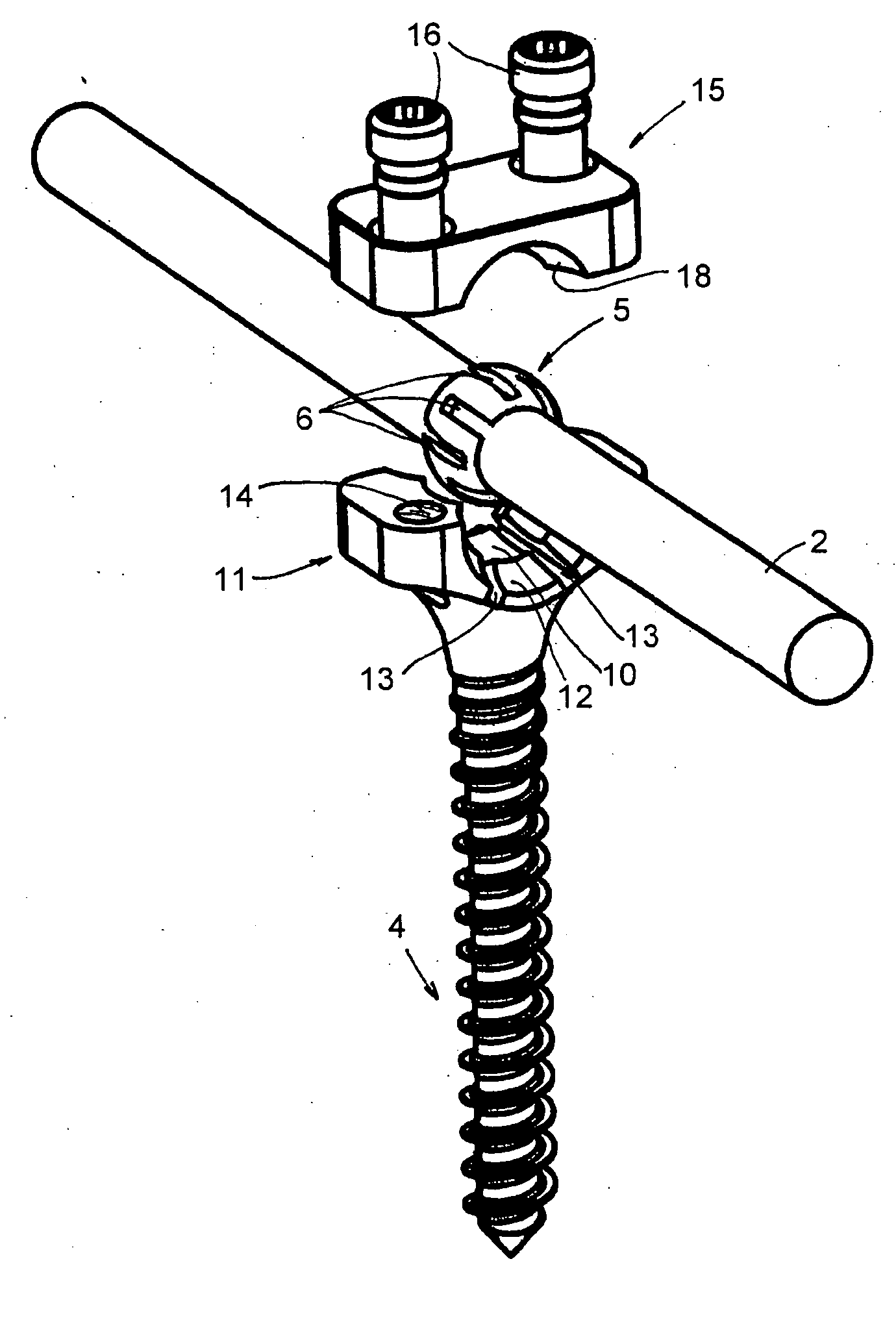
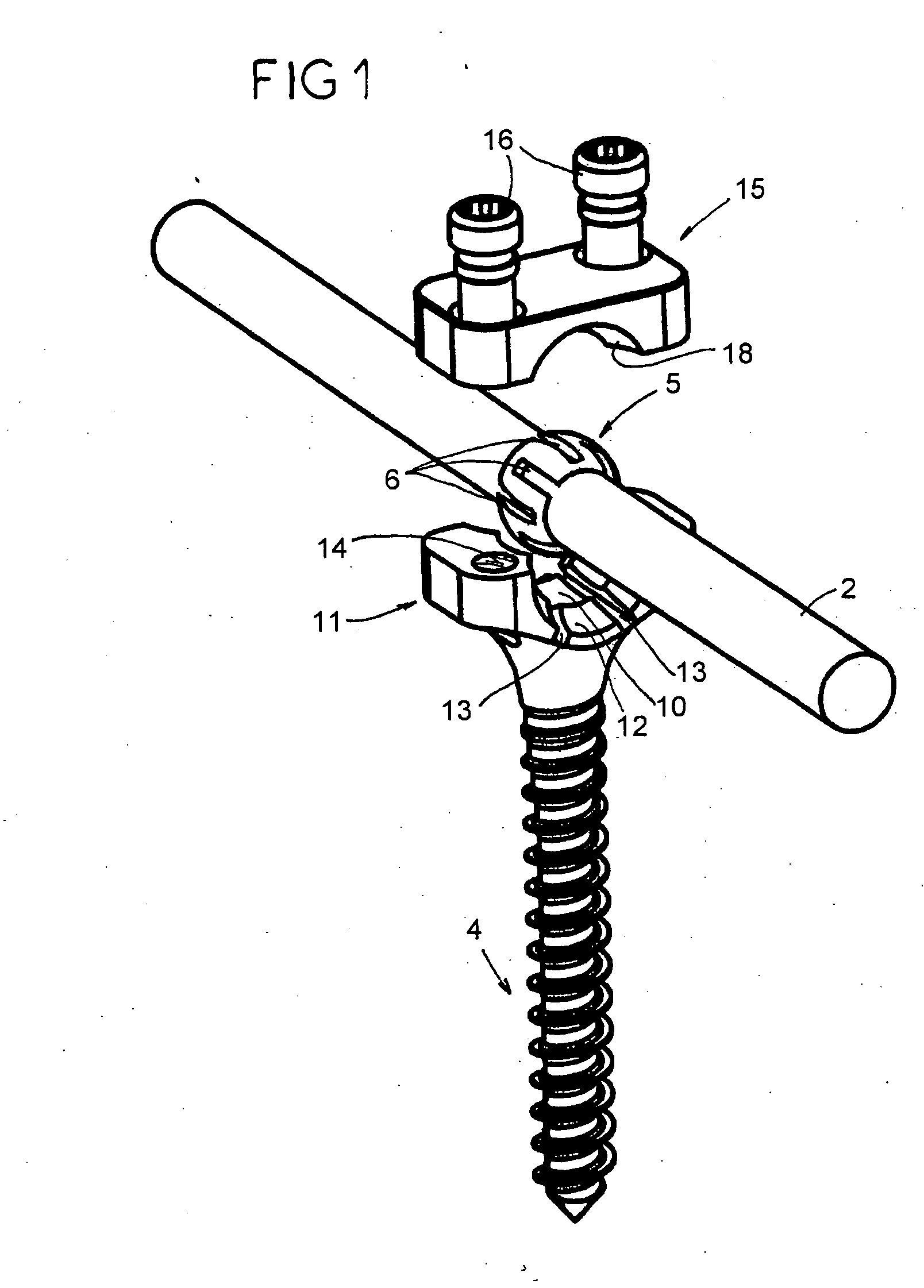
[0018]FIG. 4 represents a vertebral arthrodesis device 1 comprising one or two pins 2 for staying to the vertebral column, designed to be positioned along the vertebrae 3 that are to be immobilized, and pedicle screws 4 for anchoring this or these pins 2 to the vertebrae 3.

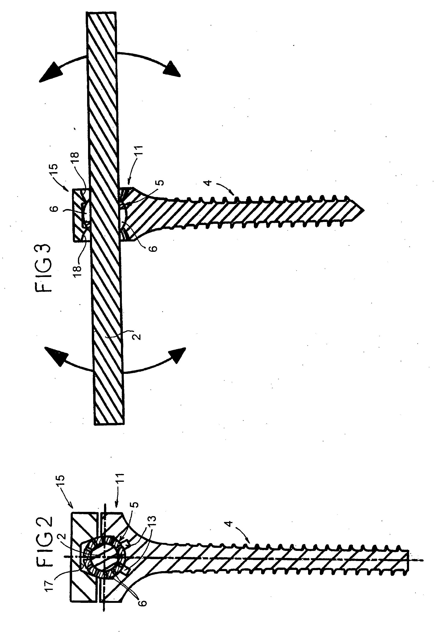
[0019] As shown in FIGS. 1 to 3, the device also comprises rings 5 of a spherical form in a number equal to that of the pedicle screws 4. FIG. 1 more particularly shows that each ring 5 presents an inside diameter allowing its sliding engagement on a pin 2 and a plurality of slots 6 distributed on its periphery. These slots 6 extend between the outer surface of the ring 5 and the said inside diameter and open alternatively at one of the longitudinal openings of this inside diameter and at the other of these longitudinal openings.

[0020] Each pin 2 is metallic and presents a cylindrical form. The pin may be curved according to the correction of the vertebral column to be performed, as well as that appearing in FIG...


PUM


Abstract

The device includes at least one pin and parts for anchoring this pin to the vertebrae. The device includes spherical rings having a plurality of slots distributed on their peripheries. The head of each anchoring part has a cavity that may receive one of the rings with snap-on installation, and at least two lateral threaded holes. Each anchoring part includes a clamping ring presenting a central aperture in a conical form allowing the clamping ring to come into contact with the ring during tightening of the screws that are within the clamping ring.

Description

FIELD OF THE INVENTION [0001] The present invention relates to a device for vertebral arthrodesis. DESCRIPTION OF THE RELATED PRIOR ART [0002] Such a device comprises, as is well known, one or two staying pins for the vertebral column, designed to be positioned along the vertebrae that are to be immobilized, and parts for anchoring this or these pins to the vertebrae. These anchoring parts are generally constituted of pedicle screws or hooks whose heads delimit the receiving cavities of the pins and receive the clamping rings of a pin in these cavities. [0003] A construction has been devised which allows the possibility of clearing a staying pin with relation to a pedicle screw and the possibility of immobilizing this pin with relation to this screw in a position in which the pin is not perpendicular to the axis of the screw. A known pedicle screw of this type presents a spherical head pierced by a hole through which the pin is designed to be engaged, this hole being threaded and re...

Claims


Application Information

Patent Timeline
Patent Type & Authority Applications(United States)
IPC IPC(8): A61B17/70
CPCA61B17/704A61B17/7032
Inventor SGIER, FREDERICMARTIN, JEAN-JACQUES
Owner PARADIGM SPINE LLC
Why Eureka
Try Eureka