
Intraocular lens injector

a technology of injectors and intraocular lenses, applied in the field of intraocular lens injectors, can solve problems such as vision deterioration

Inactive Publication Date: 2005-08-04
ALCON INC
View PDF11 Cites 16 Cited by
  • Summary
  • Abstract
  • Description
  • Claims
  • Application Information

AI Technical Summary

Benefits of technology

[0010] It is a further object of the present invention to provide a lens injector useful for stretching and implanting the ring portion of a two component intraocular lens.

Problems solved by technology

When trauma, age or disease cause the lens to become less transparent, vision deteriorates because of the diminished light which can be transmitted to the retina.

Method used


Image

  • Intraocular lens injector
  • Intraocular lens injector
  • Intraocular lens injector

Examples


Embodiment Construction

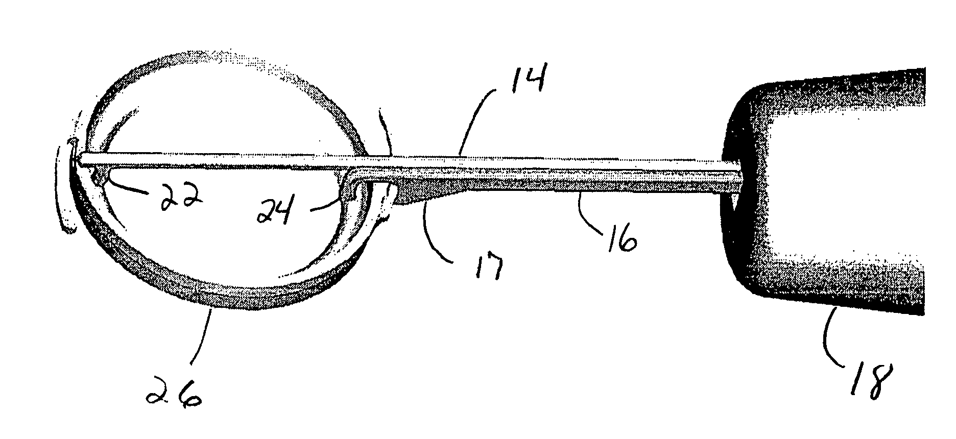
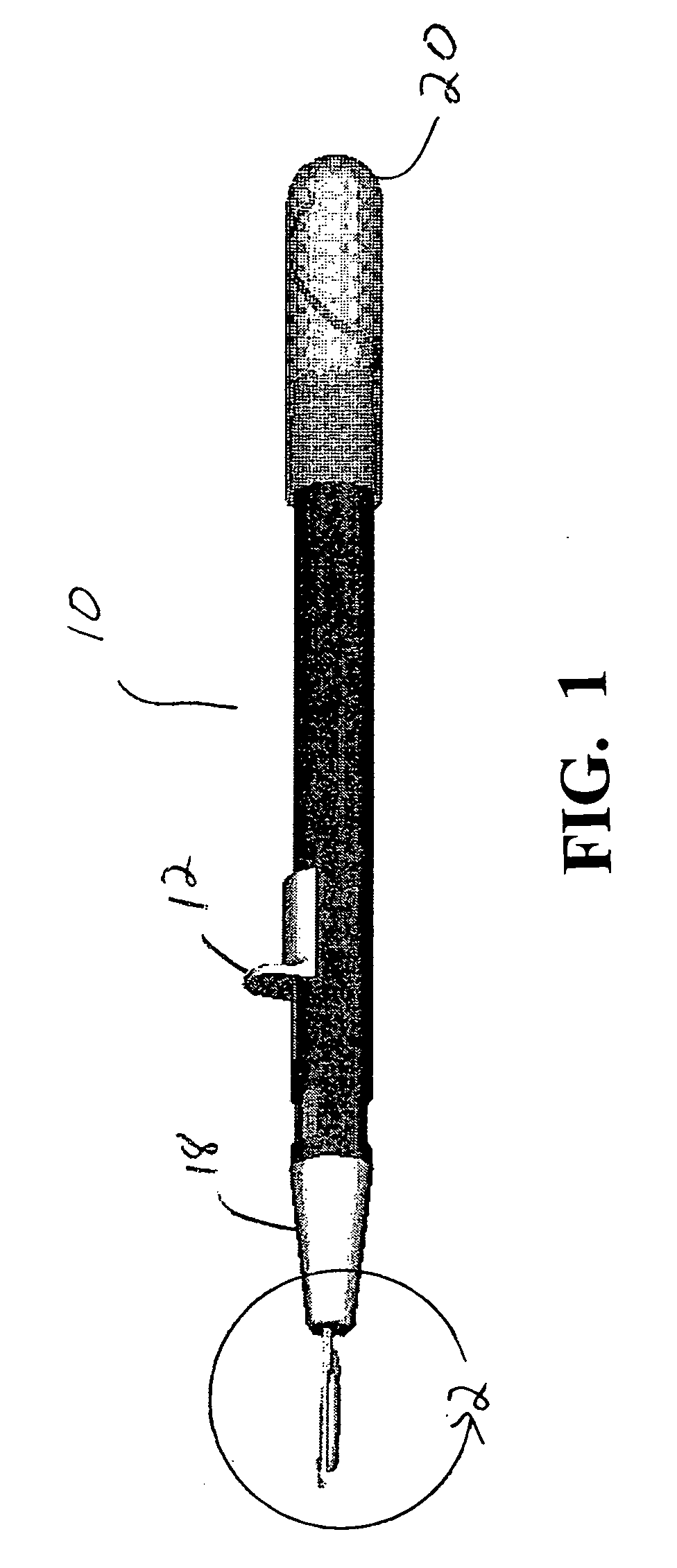
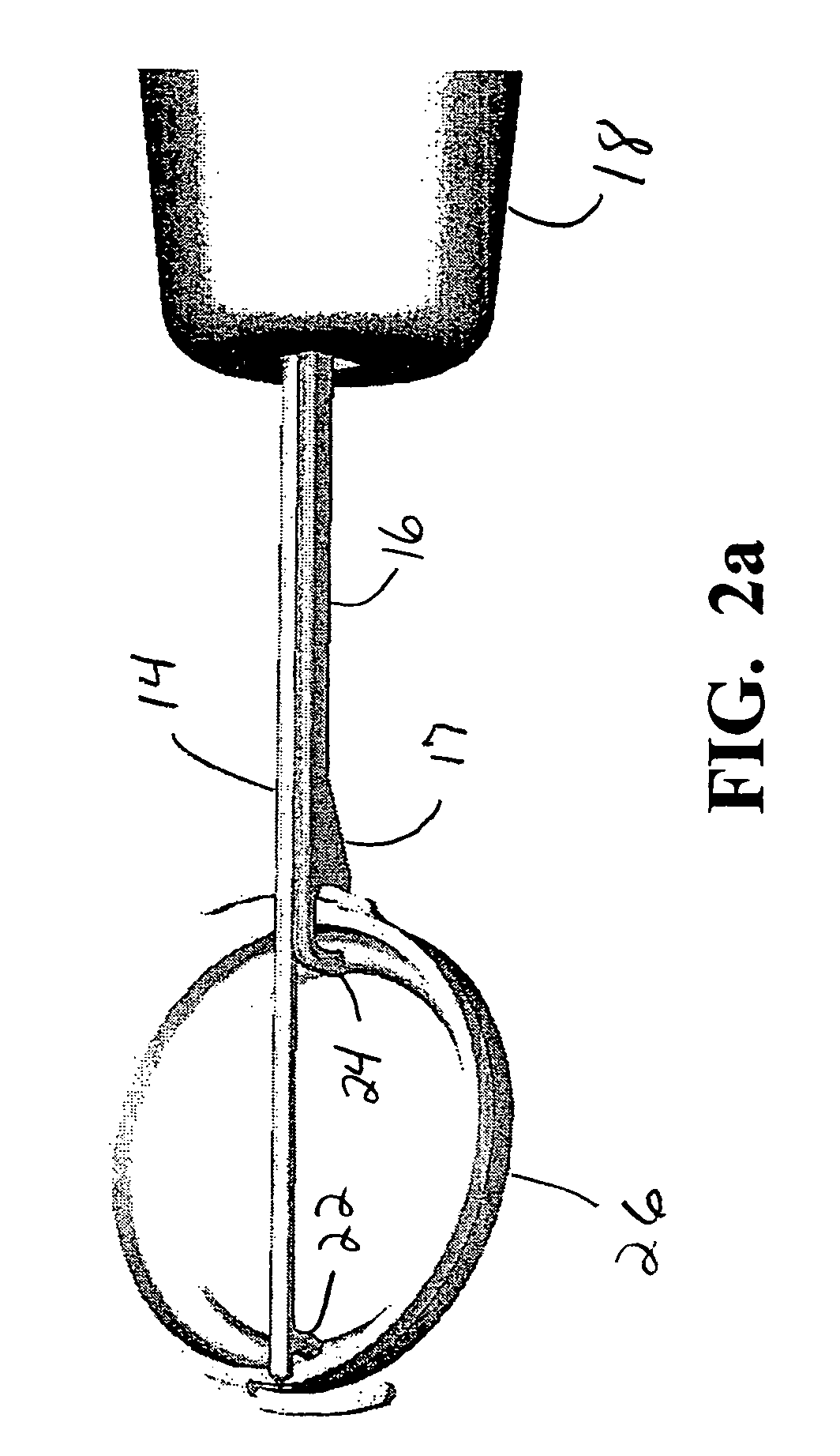
[0020] As best seen in FIGS. 1, 2a and 2b, intraocular lens injector 10 of the present invention generally consist of handpiece 10 and stretcher bars 14 and 16. Handpiece 10 contains reciprocating thumb slide 12, nosepiece 18 and extendable grip 20. Grip 20 may be extended or retracted so as to fit the hand of the user more comfortable. Stretcher bar 14 is fixed to nosepiece 18 while stretcher bar 16 penetrates through nosepiece 18 and is fixed to thumb slide 12, so that reciprocation of thumb slide 12 causes corresponding reciprocation of stretcher bar 16 relative to stretcher bar 14. Thumb slide 12 may be spring biased in either direction and may be operated by means other than manual manipulation, such as electrically or pneumatically. Stretcher bar 14 contains hook 22 and stretcher bar 16 contains hook 24. Stretcher bars 14 and 16 are preferably made from titanium, stainless steel or thermoplastic.

[0021] As best seen in FIGS. 2a and 2b, intraocular lens injector 10 is best used...


PUM


Abstract

A device having a pair of stretcher bars. The first bar remains fixed while the second bar can be reciprocated relative to the first bar by actuation of a movable slide. The device of the present invention is useful for stretching and implanting the ring portion of a two component intraocular lens.

Description

[0001] This invention relates to intraocular lenses (IOLs) and more particularly to injectors used to inject IOLs into an eye. BACKGROUND OF THE INVENTION [0002] The human eye in its simplest terms functions to provide vision by transmitting and refracting light through a clear outer portion called the cornea, and further focusing the image by way of the lens onto the retina at the back of the eye. The quality of the focused image depends on many factors including the size, shape and length of the eye, and the shape and transparency of the cornea and lens. [0003] When trauma, age or disease cause the lens to become less transparent, vision deteriorates because of the diminished light which can be transmitted to the retina. This deficiency in the lens of the eye is medically known as a cataract. The treatment for this condition is surgical removal of the lens and implantation of an artificial lens or IOL. [0004] While early IOLs were made from hard plastic, such as polymethylmethacry...

Claims


Application Information

Patent Timeline
IPC IPC(8): A61F2/16
CPCA61F2/1664A61B17/0231A61F9/00736
Inventor TRAN, SONHICKINGBOTHAM, DYSON
Owner ALCON INC
Learn More