Wiring structure, and fabrication method of the same

a technology of wiring structure and fabrication method, which is applied in the direction of magnets, magnet bodies, and heads with metal sheet cores, etc., can solve the problems of high possibility of short-circuit, low reliability of coils, and poor step coverage of insulating layers

Inactive Publication Date: 2005-08-11
CANON KK
View PDF7 Cites 34 Cited by
  • Summary
  • Abstract
  • Description
  • Claims
  • Application Information

AI Technical Summary

Problems solved by technology

Hence, droop due to fluidity of the paste is likely to occur prior to or at the time of sintering, and a short-circuit is likely to occur between adjacent wires, resulting in a decreased reliability of the coil.
In the method of JPALO-2001-250723, therefore, step coverage of the insulating layer is likely to become bad at the outermost periphery of the coil, and there is a high possibility of occurrence of a short-circuit when another coil or the like is layered on this insulating layer.
Thus, there is decreased reliability of the inter-layer insulation.

Method used


Image

  • Wiring structure, and fabrication method of the same
  • Wiring structure, and fabrication method of the same
  • Wiring structure, and fabrication method of the same

Examples


Embodiment Construction

[0020] Embodiments and examples of an electrical wiring structure of the present invention will be described with reference to FIGS. 1A through 5.

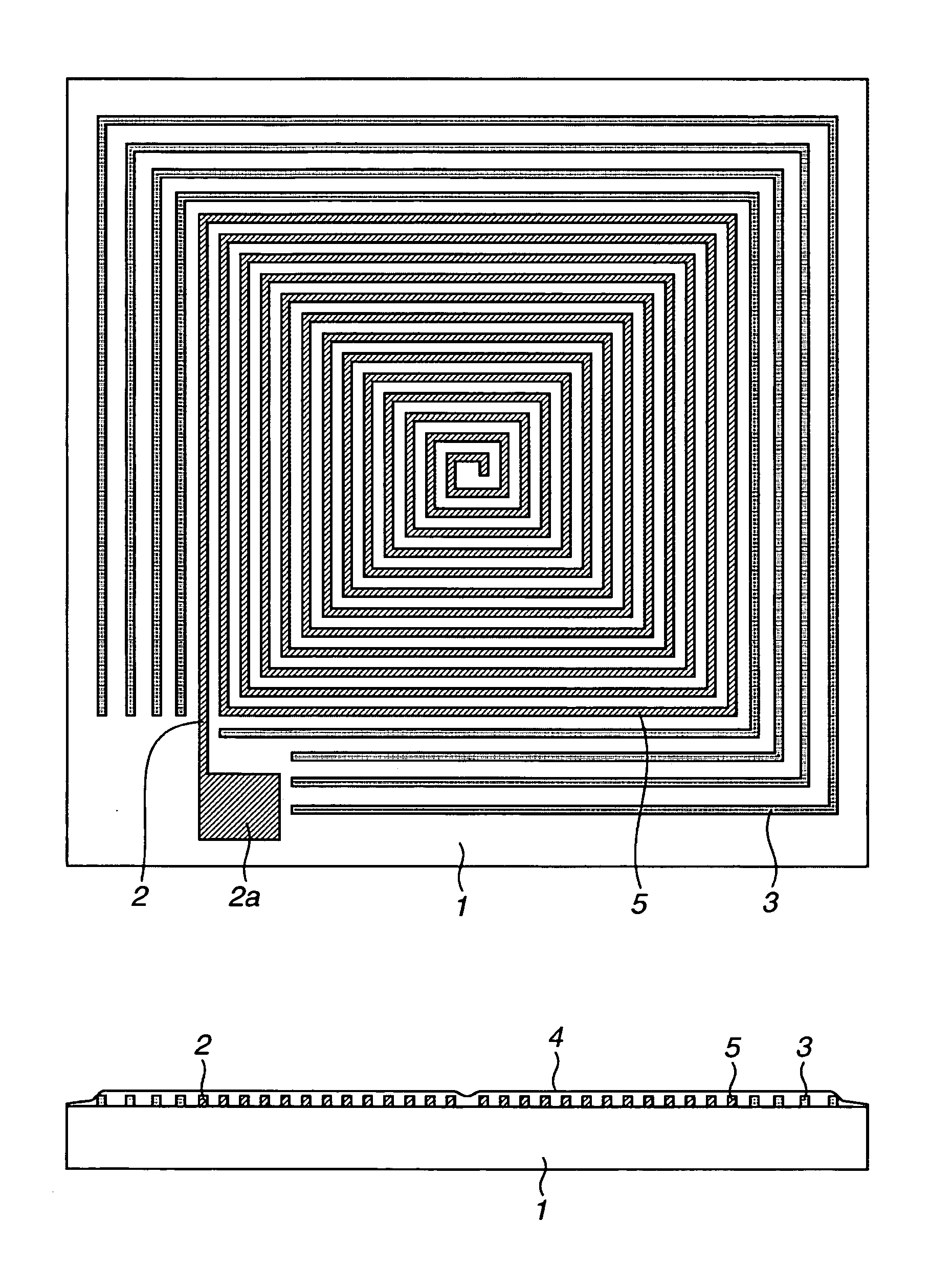
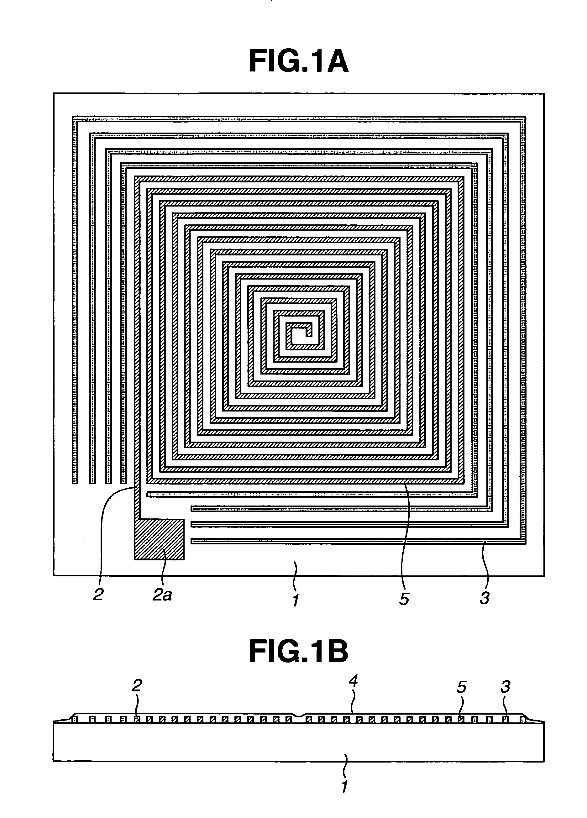
[0021] In a typical embodiment of an electrical wiring structure, a set of wiring is constructed as a spiral planar coil composed of an electrical conductor. A dam-up wall structure is provided around the periphery of the wiring such that degradation of step coverage or the like due to fall of an insulating layer can be prevented. The dam-up wall structure is preferably an electrical conductor wall structure that is not electrically connected with the wiring, such as a coil, and is formed of the same material as the wiring or coil. The dam-up wall structure can have any configuration that can serve to dam up the insulating layer and prevent the fall thereof. The dam-up wall structure is not limited to a conductor wall, and can be an insulator wall structure. Further, the dam-up wall structure can have a multi-wall structure, and can be fo...


PUM

PropertyMeasurementUnit
thicknessaaaaaaaaaa
thicknessaaaaaaaaaa
relative permittivityaaaaaaaaaa

Abstract

An electrical wiring structure, such as a planar coil, includes a set of wiring formed of an electrical conductor and formed on an insulating surface of a substrate. A dam-up wall structure is provided around an outermost peripheral portion of the set of wiring on the substrate. The dam-up wall structure is electrically disconnected from the set of wiring. An insulating layer is formed over an area from the set of wiring to the dam-up wall structure on the substrate, wherein the dam-up wall structure dams up the insulating layer.

Description

[0001] This application claims priority from Japanese Patent Application No. 2003-384612 filed Nov. 14, 2003, which is hereby incorporated by reference. BACKGROUND OF THE INVENTION [0002] 1. Field of the Invention [0003] The present invention relates to an electrical wiring structure, such as a planar coil. More particularly, the present invention relates to an electrical wiring structure, such as a planar coil, capable of being also constructed as a multi-layer structure having a reliable insulation, especially a reliable inter-layer insulation, and a fabrication method of the electrical wiring structure. The present invention also relates to an electrical wiring structure, such as a single-layer planar coil, having a reliable insulation. [0004] 2. Description of the Related Background Art [0005] In recent years, electronic equipment has been increasingly reduced in the size and thickness. In synchronization therewith, the density of an electrical wiring on a circuit board and the ...

Claims


Application Information

Patent Timeline
Patent Type & Authority Applications(United States)
IPC IPC(8): H01F5/00H01F17/00H01F27/32H01F41/04H05K1/16H05K3/10H05K3/28H05K3/46
CPCH01F5/003H01F17/0013H01F27/323H01F41/041Y10T29/4902H05K3/108H05K3/28H05K3/4644H05K2201/09781H05K1/165
Inventor TESHIMA, TAKAYUKISHIMADA, YASUHIRO
Owner CANON KK
Why Eureka
Try Eureka