Terrestrial wave receiving antenna device and antenna gain adjusting method

a technology of receiving antenna and antenna unit, which is applied in the direction of antennas, antenna details, basic electric elements, etc., can solve the problem of directional gain of antennas that tend to decreas

Inactive Publication Date: 2005-08-11
NIPPON SHEET GLASS CO LTD
View PDF6 Cites 2 Cited by
  • Summary
  • Abstract
  • Description
  • Claims
  • Application Information

AI Technical Summary

Benefits of technology

[0005] An object of the present invention is to provide a ground wave reception antenna unit which does not cause a decrease in a directional gain during the reception of a vertically polarized wave even when an antenna is positioned inclining from a vertical direction.

Problems solved by technology

In such a case, when a vertically polarized wave propagating in a horizontal direction is to be received, there is a problem in that a directional gain of an antenna tends to decrease, since an effective aperture area of the antenna decreases due to the slope of the antenna.

Method used


Image

  • Terrestrial wave receiving antenna device and antenna gain adjusting method
  • Terrestrial wave receiving antenna device and antenna gain adjusting method
  • Terrestrial wave receiving antenna device and antenna gain adjusting method

Examples


Embodiment Construction

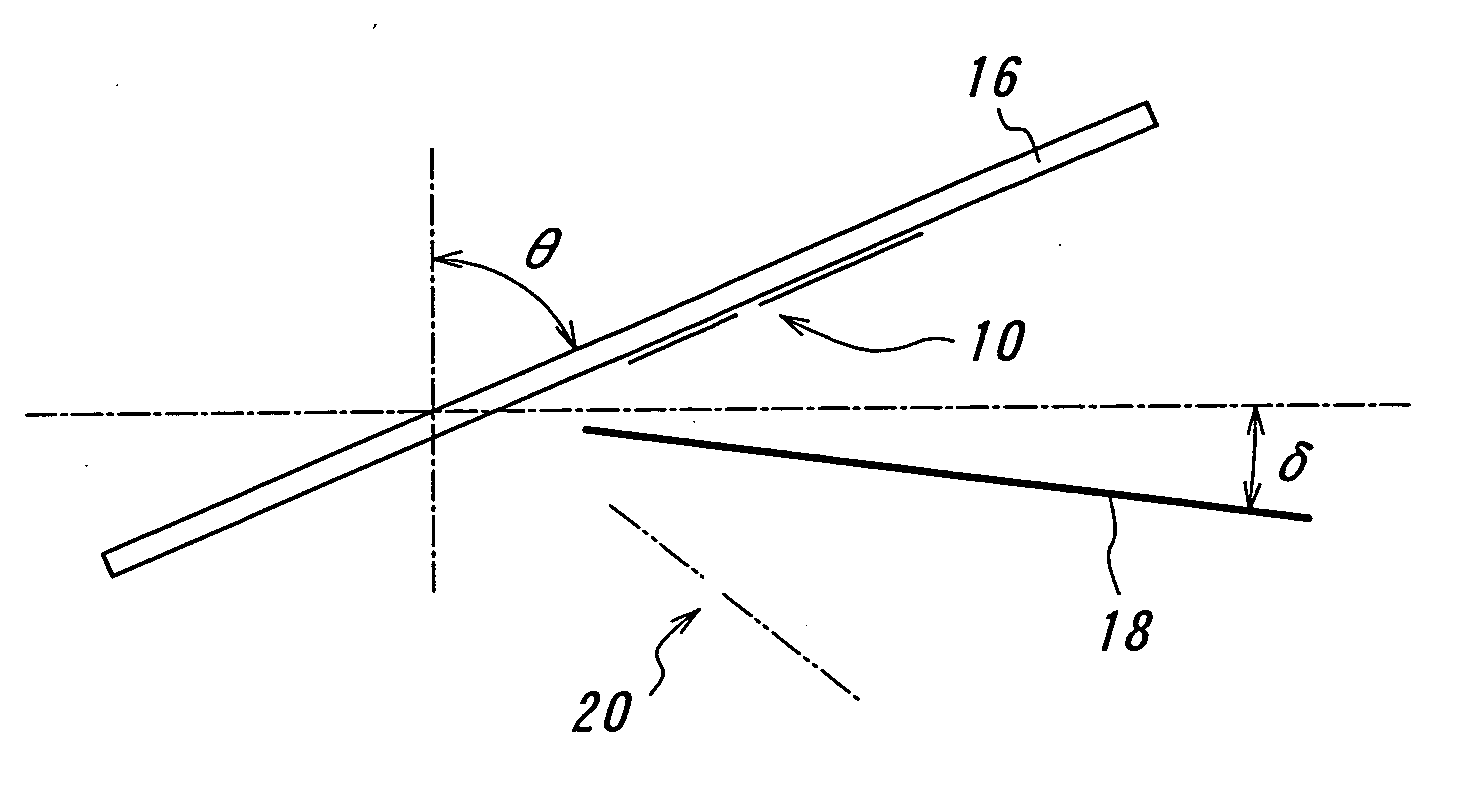
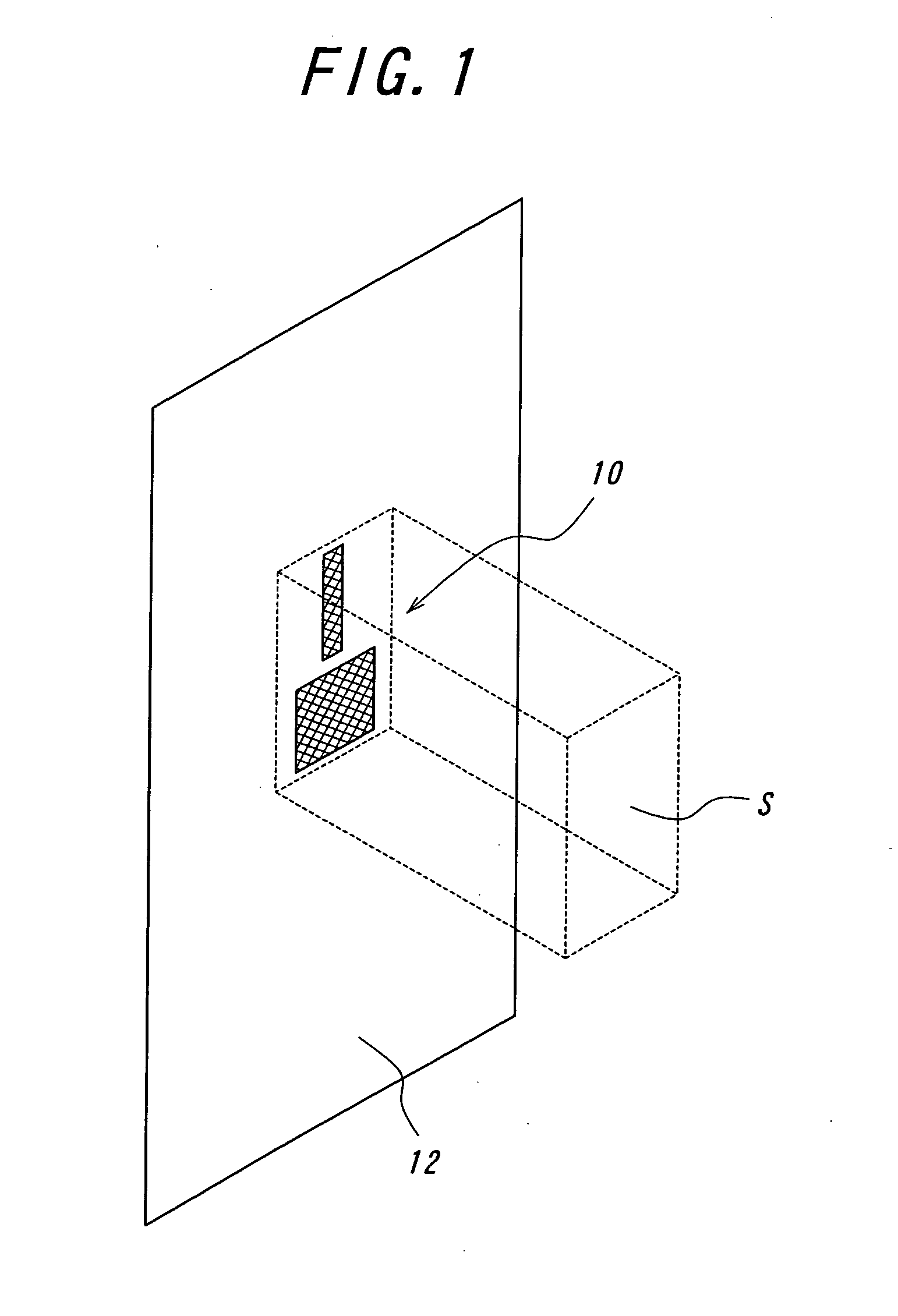
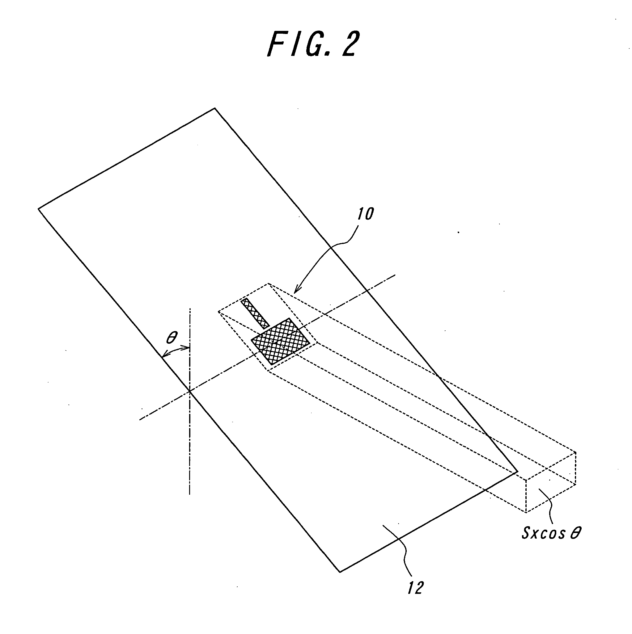
[0023]FIG. 3 shows one embodiment of a ground wave reception antenna unit of the present invention. A planar antenna 10 is provided on a glass plate 16 which is sloped by an angle of θ from a vertical direction. In the case where the antenna unit is mounted on a vehicle, the glass plate corresponds to a front glass or rear glass.

[0024] This ground wave reception antenna unit comprises a reflector positioned under the planar antenna 10, the reflector extending in a horizontal direction or inclining by an angle of δ (0-30°) from a horizontal direction with being spaced from the planar antenna. In this embodiment, the reflector is positioned inclining from a horizontal direction by 6°. A reflected image antenna 20 is formed by the reflector 18 positioned inclining from a horizontal direction, and an effective aperture area for a vertically polarized wave propagating in a horizontal direction apparently increases from S×cos θ, In this way, a directional gain for a vertically polarized ...


PUM


Abstract

A ground wave reception antenna unit is provided, in which a directional gain during the reception of a vertically polarized wave does not decrease. The antenna unit comprises a planar antenna positioned inclining from a vertical direction and a reflector positioned in a horizontal direction or inclining from a horizontal direction by a predetermined angle with being spaced from the planar antenna by a predetermined distance. The reflector is positioned in close proximity to the planar antenna, or is positioned at a distance of integer multiples of 0.5λ, wherein λ is a wavelength of a ground wave received by the planar antenna.

Description

TECHNICAL FIELD [0001] The present invention relates generally to a ground wave reception antenna unit and a method for adjusting a gain of the antenna unit, particularly to a ground wave reception antenna unit comprising an antenna body positioned inclining from a vertical direction and a method for adjusting a gain of such an antenna unit. BACKGROUND ART [0002] There are some cases where an antenna body has to be positioned inclining from a vertical direction in view of circumstances where an antenna unit for receiving a wave (a vertically polarized wave) from a ground-based station is provided. One example is the case where a glass antenna for a vehicle is provided. Particularly, the slope of a front glass, a rear glass or the like of a vehicle is large so that the antenna body positioned on the glass is inevitably inclined. [0003] In such a case, when a vertically polarized wave propagating in a horizontal direction is to be received, there is a problem in that a directional gai...

Claims


Application Information

Patent Timeline
Patent Type & Authority Applications(United States)
IPC IPC(8): H01Q1/12H01Q19/10
CPCH01Q1/1271H01Q19/104H01Q19/10
Inventor OSHIMA, HIDEAKITAKEDA, YOICHI
Owner NIPPON SHEET GLASS CO LTD
Why Eureka
Try Eureka