Plasma generator

a plasma generator and high-frequency discharge technology, applied in plasma techniques, electric discharge tubes, antennas, etc., can solve the problems of inability to compensate the electron current lost from the plasma, and the stoppage of the ion beam irradiation device for maintenance for a long tim

Inactive Publication Date: 2014-02-13
NISSIN ION EQUIP CO LTD
View PDF0 Cites 1 Cited by
  • Summary
  • Abstract
  • Description
  • Claims
  • Application Information

AI Technical Summary

Benefits of technology

[0015]One plasma generator according to this invention makes the PFG current Ipfg not decrease by ionizing a gas using high-frequency discharge within a plasma generating chamber to generate plasma and discharge electrons externally from that plasma through an electron discharge hole, equipping the plasma generator with an antenna installed in the plasma generating chamber that radiates high-frequency waves and an antenna cover that covers the entire antenna and is comprised of an insulating material, in a plasma generator in which the plasma electrode material that has the electron discharge hole is comprised of conductive material, between the plasma electrode and the antenna, in the cylindrical frame region, a frame cover is provided that has protrusions of different thicknesses that are on the inner side or the inner and outer sides of the frame, the material of the frame cover being an insulating material, the frame cover protrusions that are near the top surface of the plasma electrode that is near the frame cover forming shadows near the top surface of the plasma electrode, and those shadows preventing accumulation of insulating material on the plasma electrode due to sputtering by the plasma.

Problems solved by technology

This results in stoppage of the ion beam irradiation device for maintenance for a long time.
Although the ions can obtain the electrons by recombining in the plasma, the electron current lost from the plasma cannot be compensated.

Method used


Image

  • Plasma generator
  • Plasma generator
  • Plasma generator

Examples


Embodiment Construction

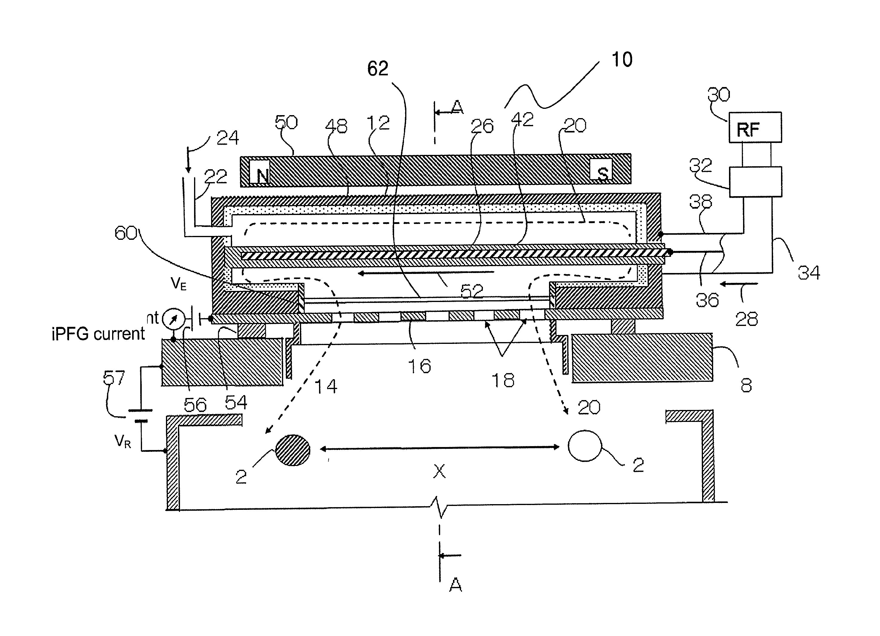
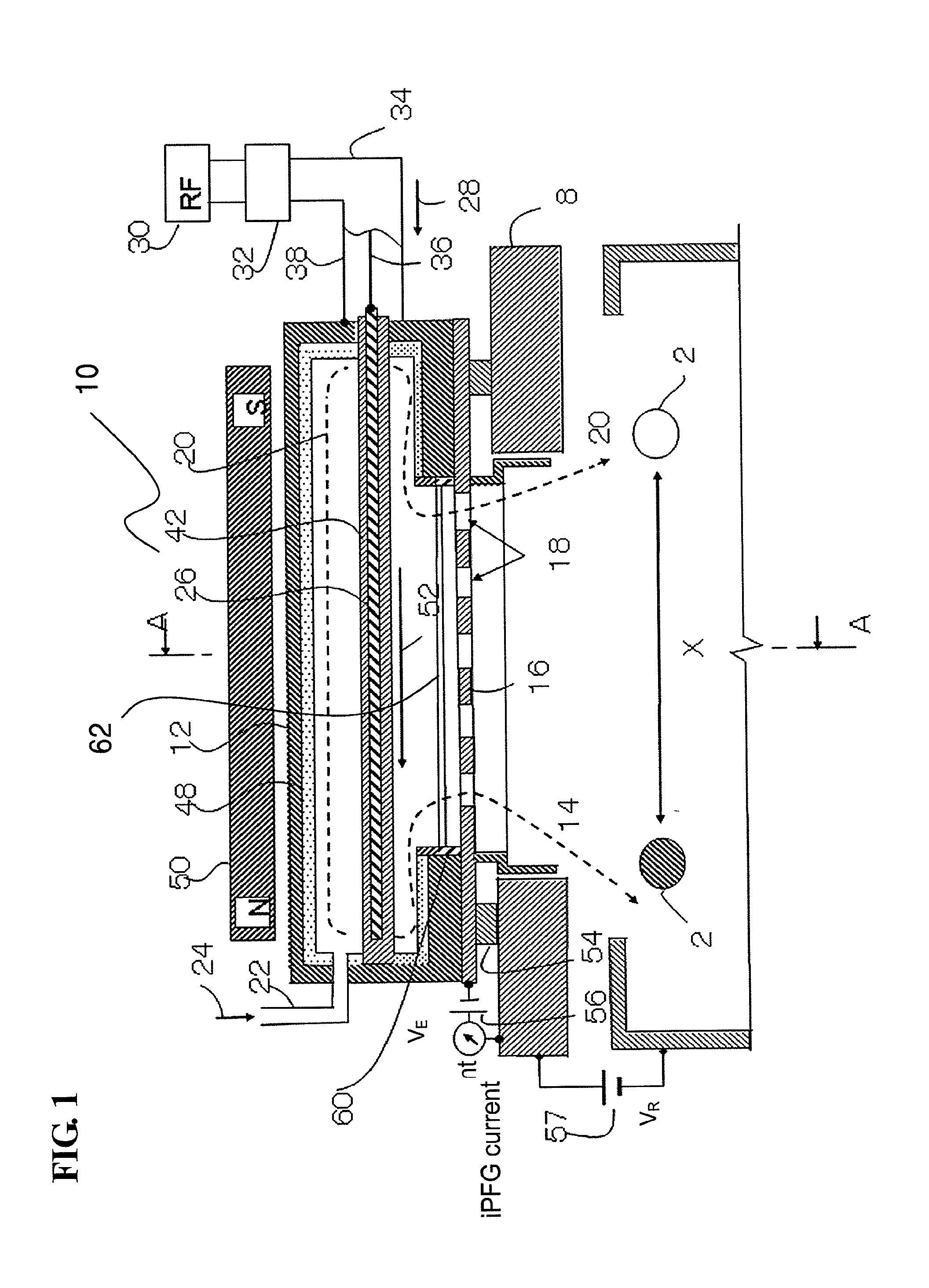
[0025]Exemplary embodiments of a plasma generator according to the present invention are explained below with reference to the accompanying drawings. In FIGS. 1 and 2, a configuration is explained as an example in which a plasma generator 10 is used in an ion beam irradiation device (this device is called an ion implantation apparatus when ion implantation is performed) that performs a process of ion implantation, etc., into a substrate 4 by irradiating the substrate (for example, semiconductor substrate) 4 with an ion beam 2 in a target chamber 8. The plasma generator 10 is attached outside the target chamber 8 located in the vicinity of an upstream side of the substrate 4 via an insulator 54.

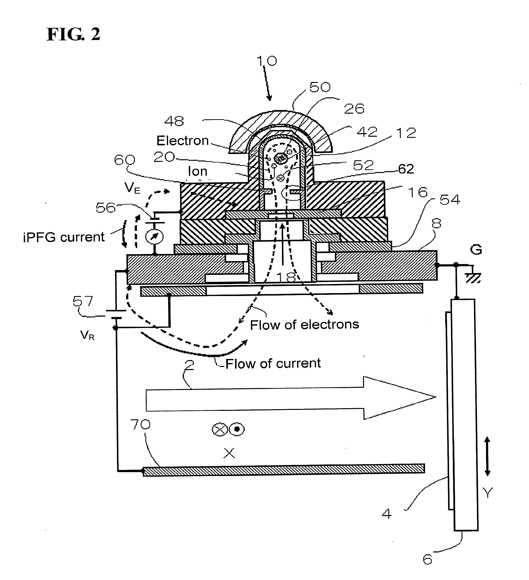
[0026]In this example, the ion beam 2 is reciprocally scanned in an X direction (for example, horizontal direction) by the action of an electric field or a magnetic field. The substrate 4 is secured to a holder 6, and reciprocally scanned in a mechanical manner in a Y direction (for example, o...


PUM


Abstract

A plasma generator generates a plasma by ionizing a gas with a high-frequency discharge in a plasma generating chamber so that electrons from the plasma are emitted outside the plasma generator through an electron emitting hole. The plasma generator includes an antenna that is provided in the plasma generating chamber and that emits a high-frequency wave, and an antenna cover that is made of an insulating material and that covers an entire body of the antenna. A plasma electrode having the electron emitting hole is made of a conductive material. A frame cover with a protrusion ensures conductivity by preventing an insulating material from accumulating on a surface of the plasma electrode on a plasma side in sputtering by the plasma.

Description

BACKGROUND OF THE INVENTION[0001]This application is a continuation-in-part of U.S. patent application Ser. No. 13 / 198,429, filed Aug. 4, 2011, claiming priority to Japanese Patent Application No. 2010-186824, filed Aug. 24, 2010, the contents of which is incorporated by reference in its entirety.[0002]1. Field of the Invention[0003]The present invention relates to a high-frequency discharge plasma generator that is used for suppressing an electrostatic charge (charge-up), etc., on a surface of a substrate when ion beam irradiation is carried out in an ion beam irradiation device that performs ion implantation, etc., by, for example, irradiating the substrate with an ion beam.[0004]2. Description of the Related Art[0005]A plasma generator is disclosed in Japanese Patent Application Laid-open No. 2002-324511 (Paragraphs 0031 to 0038 and FIG. 1) as an example of a high-frequency discharge plasma generator described above used for suppressing an electrostatic charge on a surface of a s...

Claims


Application Information

Patent Timeline
Patent Type & Authority Applications(United States)
IPC IPC(8): H05H1/46
CPCH05H1/46H01J37/3211H01J37/32357H01J37/32541H05H1/463H05H1/4652
Inventor FUJITA, HIDEKIIGO, TETSUYA
Owner NISSIN ION EQUIP CO LTD
Why Eureka
Try Eureka