System for insertion and extraction of a printed circuit board module into and out of a subrack

a technology of printed circuit board modules and subracks, which is applied in the direction of electrical apparatus construction details, casings/cabinets/drawers, casings/cabinets/drawers details, etc., can solve the problems of large forces affecting the stress on the plug-in modules, the inability to perform the addition, replacement or upgrading of plug-in modules in electronic equipment subracks/racks, and the increase in the number and density of connectors on the subracks

Inactive Publication Date: 2005-08-11
PEP WEST
View PDF11 Cites 48 Cited by
  • Summary
  • Abstract
  • Description
  • Claims
  • Application Information

AI Technical Summary

Problems solved by technology

As the complexity and functionality of plug-in modules have increased in the past several years, the demands for connector capacity have increased, thereby increasing the number and density of the connectors on the subracks and plug-in modules.
Such large forces due to both connectors and other mating components can be difficult to apply during insertion and extraction of plug-in modules, thus making it difficult to perform the addition, replacement or upgrading of plug-in modules in electronic equipment subracks/racks.
Further, the application of such large forces creates stresses on the plug-in modules, the printed circuit boards within the plug-in modules and the subracks supporting the plug-in modules.
In particular, the forces and stresses exerted on the printed circuit boards can cause deformation of the printed circuit boards or cause components to dislodge from the boards.
Further, the forces and stresses exerted on the subracks can cause deflection of the

Method used


Image

  • System for insertion and extraction of a printed circuit board module into and out of a subrack
  • System for insertion and extraction of a printed circuit board module into and out of a subrack
  • System for insertion and extraction of a printed circuit board module into and out of a subrack

Examples


Embodiment Construction

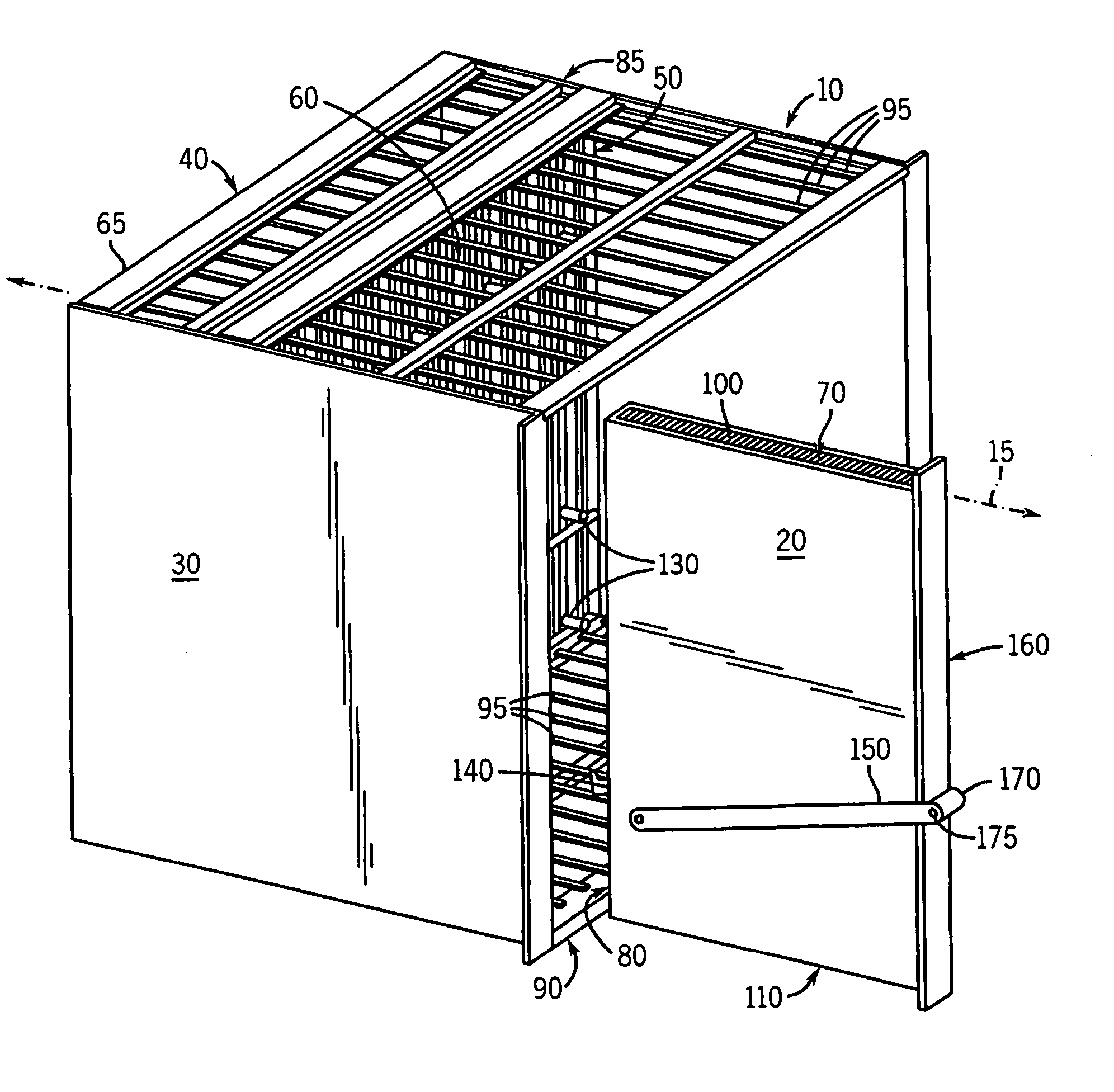
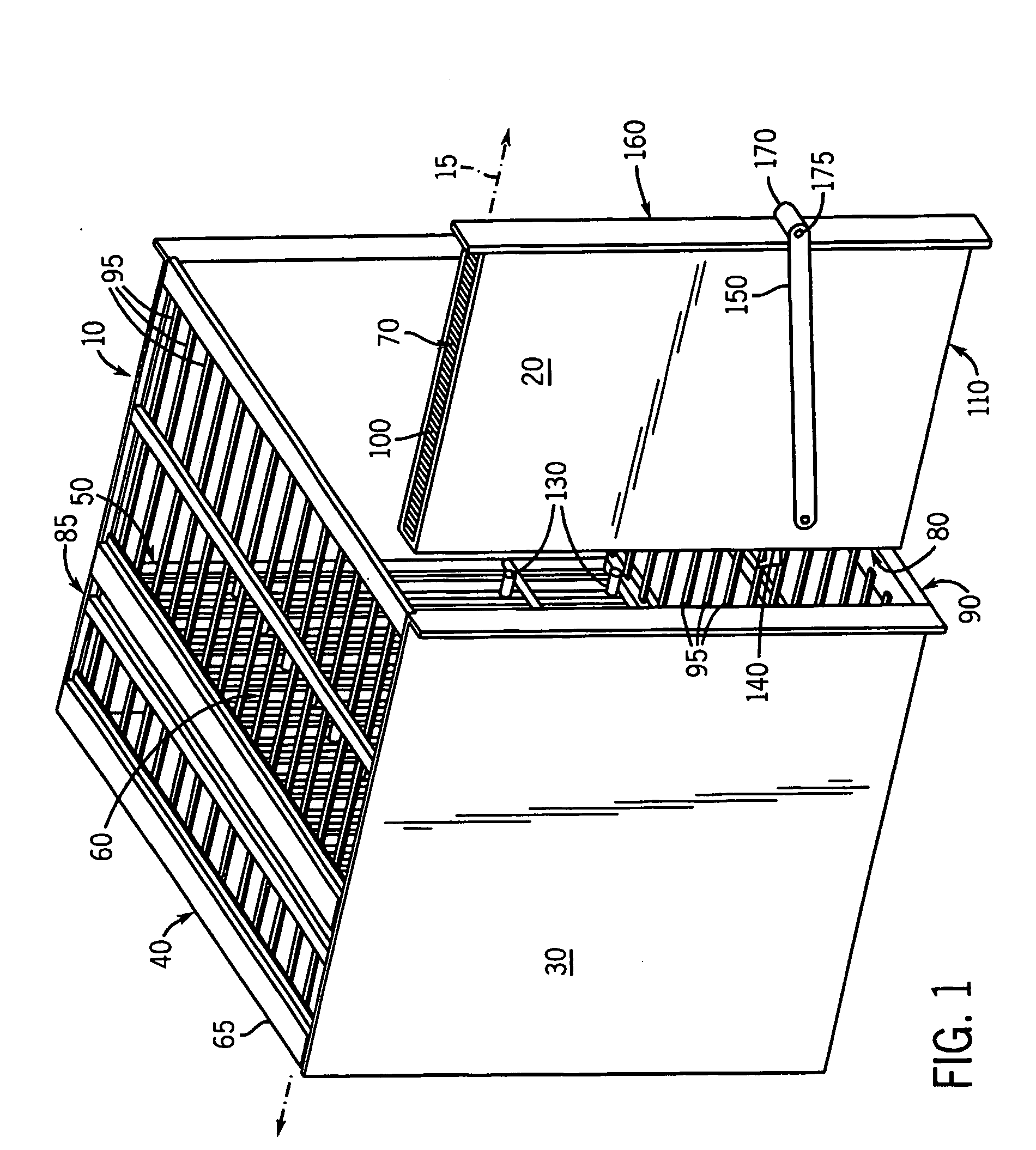
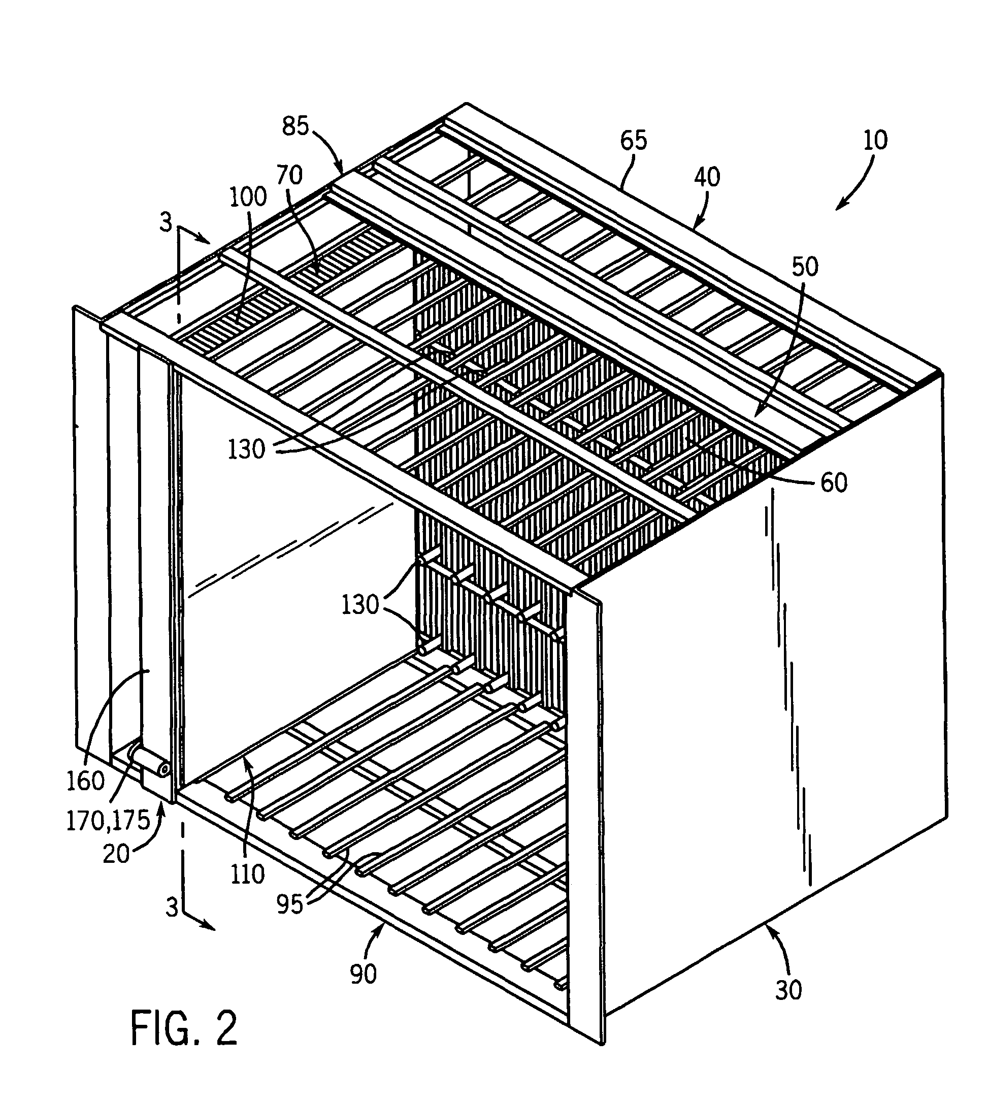
[0021] Referring to FIGS. 1 and 2, an exemplary subrack 10 is shown in conjunction with a plug-in module 20 that is capable of being inserted into and extracted from the subrack. More specifically, FIG. 1 shows the plug-in module 20 separated from the subrack 10, prior to its insertion into the subrack or after its extraction from the subrack, while FIG. 2 shows the plug-in module in its fully-inserted position within the subrack. In the embodiment shown, the subrack 10 includes walls 30 and other structural support components 40. In alternate embodiments, the subrack 10 can include subpartitions or other components not shown, and depending upon the embodiment also can form part of a larger rack or other piece of equipment.

[0022] The subrack 10 also includes a surface 50 on which are positioned connectors 60 that are connected to various other electrical components (not shown). The surface 50 in the present embodiment is a backplane, although in alternate embodiments it could be a ...


PUM


Abstract

A system for inserting and extracting a plug-in module into and from an electronic equipment subrack is disclosed. In certain embodiments, the system includes an actuation device, an arm including a first guiding surface, and a second guiding surface on the module. At least a portion of the actuation device is located proximate a front edge of the module, while the arm is located proximate a rear edge of the module along which connectors are positioned. As the actuation device is moved in one direction, the arm is forced toward the module, causing the guiding surfaces to interact so that the arm engages a retaining component on the subrack. Opposite movement of the actuation device causes the arm to push away and disengage from the module. The actuation device in certain embodiments includes a lever and a drag link, or a push-pull rod coupled to a drag link.

Description

CROSS-REFERENCE TO RELATED APPLICATIONS [0001] This application claims the benefit of U.S. provisional patent application No. 60 / 350,415, which was filed on Jan. 21, 2002.FIELD OF THE INVENTION [0002] The present invention relates generally to electronic equipment racks and related systems, including subracks and plug-in modules with one or more printed circuit boards for insertion and removal from the subracks. More specifically, the present invention relates to systems by which the plug-in modules are inserted and extracted from the subracks. BACKGROUND OF THE INVENTION [0003] Electronic equipment subracks are commonly employed in computers, data processing and communication systems, and other devices. The subracks often are positioned within and supported by racks, which are larger cabinets for the electronic equipment. Typically, to assemble and configure such subracks for use, plug-in modules must be appropriately inserted into the subracks to establish desired electrical conne...

Claims


Application Information

Patent Timeline
IPC IPC(8): H05K5/02H05K7/14H05K7/16
CPCH05K5/023H05K7/1409H05K7/1402
Inventor DOWNING, ROBERT W.HOM, FRANKSCRIVEN, STUART M.PERAZZO, THOMAS M.
Owner PEP WEST
Why Eureka
Try Eureka