
Dual microphone communication device for teleconference

a communication device and microphone technology, applied in the direction of transducer details, transducer casings/cabinets/supports, electric transducers, etc., can solve the problems of significant drop in transmission quality, loop back transmission will produce annoying far-end echoes, and reduce interfering echoes, so as to increase the gain of the system, improve the communication quality, and improve the effect of user clarity

Inactive Publication Date: 2005-08-11
FORTEMEDIA
View PDF5 Cites 46 Cited by
  • Summary
  • Abstract
  • Description
  • Claims
  • Application Information

AI Technical Summary

Benefits of technology

[0011] At least a second objective of the present invention is to provide a dual microphone communication device and communication method for a teleconference system that maintains a high communication quality despite setting the microphone and loudspeaker close to each other.
[0012] At least a third objective of the present invention is to provide a dual microphone communication device and communication method for a teleconference system that increases the gain of the system but without triggering any howling in the system.
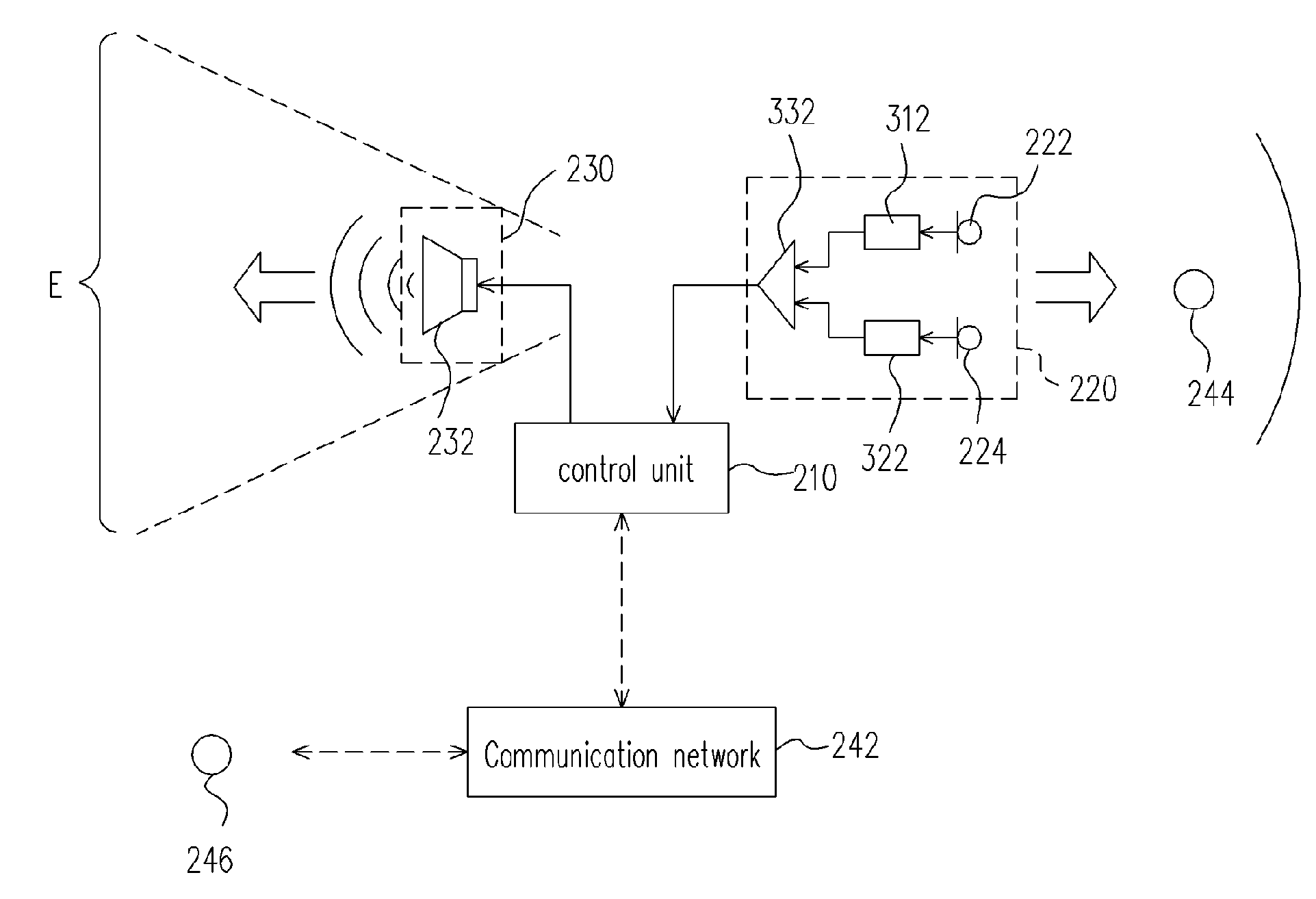
[0013] To achieve these and other advantages and in accordance with the purpose of the invention, as embodied and broadly described herein, the invention provides a dual microphone communication device for a telecommunication system in a video teleconference. The dual microphone communication device comprises a first microphone module, a second microphone module and a mixer circuit. The first microphone module receives a near-end audio signal from a user. The first microphone module amplifies the near-end audio signal to produce a first audio signal. Similarly, the second microphone module receives the near-end audio signal. However, the second microphone module has a fixed gain. Furthermore, on receiving the near-end audio signal, the second microphone module produces a second audio signal having a constant phase difference from the original near-end audio signal. The mixer circuit receives the first audio signal and the second audio signal and subtracts the second audio signal from the first audio signal to produce a third audio signal. Although the third audio signal is formed by signal subtraction, the ear of a human listener can hardly distinguish the difference between the first audio signal and the third audio signal. Hence, the third audio signal is able to suppress interfering echoes without compromising the clarity of the user.
[0025] In addition, the input module is set in a predetermined direction for receiving the near-end audio signal and the output module is set in a direction within a range just opposite to the predetermined direction. Furthermore, the direction in which the output module outputs the far-end audio signal is opposite to the direction in which the input module receives the near-end audio signal. Hence, a high communication quality can be maintained despite setting the microphone and the loudspeaker close to each other

Problems solved by technology

One of the major issues in a conventional teleconference system is the reduction of interfering echoes.
The loop back transmission will produce some annoying far-end echoes.
If there is a series system mismatch, howling sound is often produced causing a significant drop in transmission quality.
One major defect of this communication method is voice clipping.
In this way, critical parts of an important message may be lost.
When the feedback acoustic signal exceeds a largest permissible magnitude, the residual echo will be out of control, worse still, system howling can be triggered.
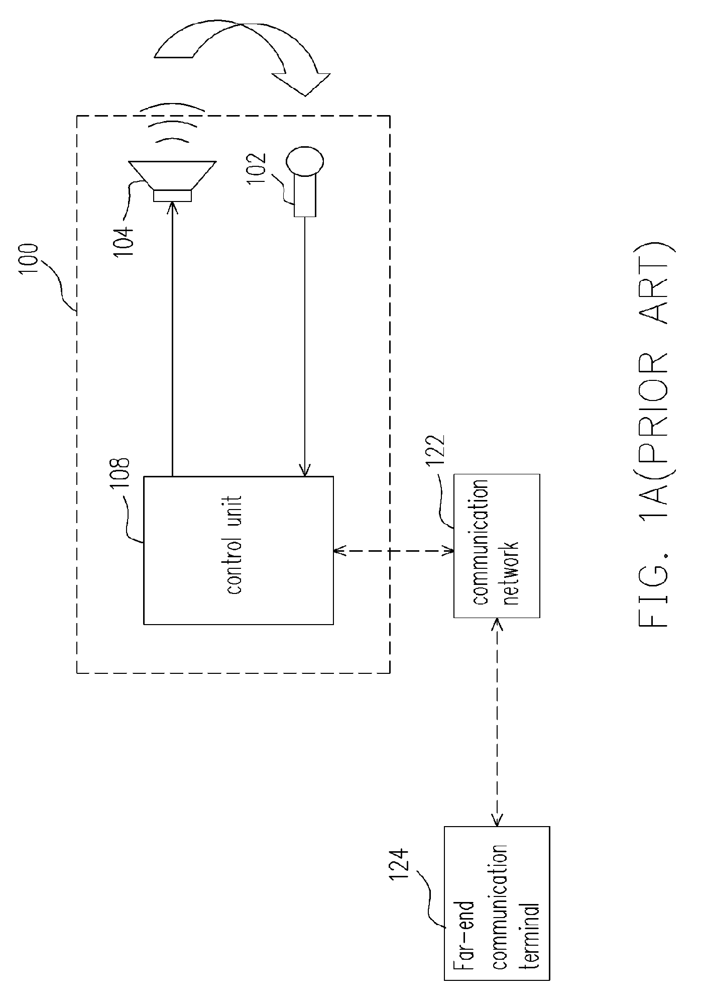
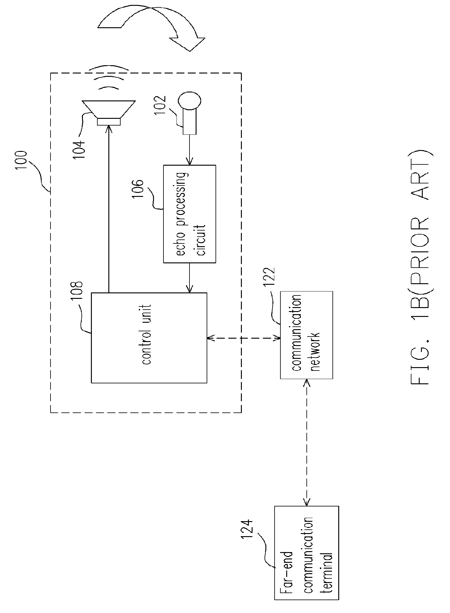
However, using this method, the listener at the far end of the line can hardly hear the sound of a user speaking at the near end if the microphone 102 is positioned at a location slightly further away from the user.
To be heard, the user may have to raise one's voice resulting in great discomfort.

Method used


Image

  • Dual microphone communication device for teleconference
  • Dual microphone communication device for teleconference
  • Dual microphone communication device for teleconference

Examples


Embodiment Construction

[0033] Reference will now be made in detail to the present preferred embodiments of the invention, examples of which are illustrated in the accompanying drawings. Wherever possible, the same reference numbers are used in the drawings and the description to refer to the same or like parts.

[0034]FIG. 2 is a schematic block diagram showing an electrical transmission system according to one preferred embodiment of the present invention. As shown in FIG. 2, a control unit 210 is coupled to an input module 220, an output module 230 and a communication network 242. A group of people 244 may use the device of this invention to communicate with another group of people 246 through a communication network 242 such as a public telephone exchange network. First, a near-end audio signal (for example, the audio frequency signal output from the output module 230 and the sound produced by the group of people 244) produced by the group of people 244 is fed into the input module 220. Thereafter, the ...


PUM


Abstract

A dual microphone communication device comprising a first microphone module, a second microphone module and a mixer circuit is provided. The first microphone module amplifies a near-end audio signal to produce a first audio signal. The second microphone module receives and amplifies the near-end audio signal by a fixed gain and a constant phase difference to produce a second audio signal. The mixer circuit subtracts the second audio signal from the first audio signal to produce a third audio signal so that interference resulting from echoes is significantly reduced while keeping, or enhance the near end voice level.

Description

CROSS-REFERENCE TO RELATED APPLICATION [0001] This application claims the priority benefit of Taiwan application serial no. 93102734, filed Feb. 06, 2004. BACKGROUND OF THE INVENTION [0002] 1. Field of the Invention [0003] The present invention relates to a dual microphone communication device. More particularly, the present invention relates to a communication device for teleconference. [0004] 2. Description of the Related Art [0005] With the advent of Internet communication, wide-area or transnational conference using a teleconference system has become a common affair especially for international companies. In the past, cooperations have to spend a large sum of money just for monitoring the business in various branches. With the introduction of teleconference, the operations in each and every branches can be effectively controlled and administrative instructions can be distributed beyond the boundaries of countries without delays. [0006]FIG. 1A is a schematic block diagram of a co...

Claims


Application Information

Patent Timeline
Patent Type & Authority Applications(United States)
IPC IPC(8): H04M9/08H04R3/00
CPCH04M9/082H04R2410/05H04R3/005
Inventor LEE, YI-BINGLI, XIAO DONG
Owner FORTEMEDIA
Learn More