Image forming apparatus

a technology of image forming apparatus and forming apparatus, which is applied in the direction of electrographic process apparatus, instruments, optics, etc., can solve the problems of more time required for copying and complicated control system structure, and achieve the effect of reducing control and reducing the number of copies of the image formed

Active Publication Date: 2005-08-11
RICOH KK
View PDF2 Cites 52 Cited by
  • Summary
  • Abstract
  • Description
  • Claims
  • Application Information

AI Technical Summary

Benefits of technology

[0012] It is an object of the present invention to solve at least the above problems in the conventional technology.
[0013] An image forming apparatus according to one aspect of the present invention includes a capacitor that is charged by a commercial power; a heating unit that is heated by power supplied by the commercial power and the capacitor; a fixing member that is heated by the heating unit, and that applies heat on an image to be fixed to fix the image on a recording medium;

Problems solved by technology

In order that each mode is use appropriately, the structure of the control system has been complicated.
Moreover, while passing the cardboard paper, a drop in temperature of the fixing member is de

Method used


Image

  • Image forming apparatus
  • Image forming apparatus
  • Image forming apparatus

Examples


Embodiment Construction

[0021] Exemplary embodiments of an image forming apparatus according to the present invention will be described in detail with reference to the accompanying drawings.

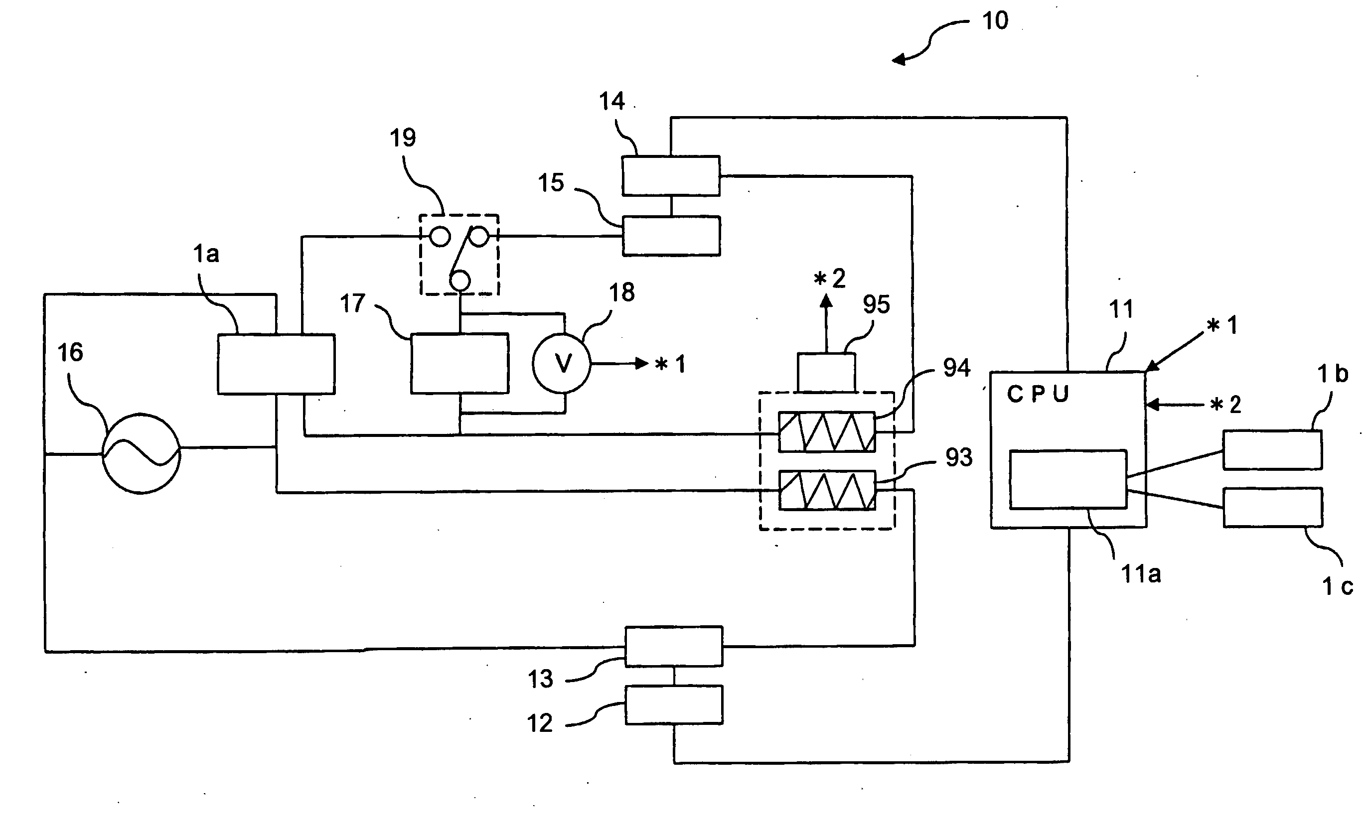
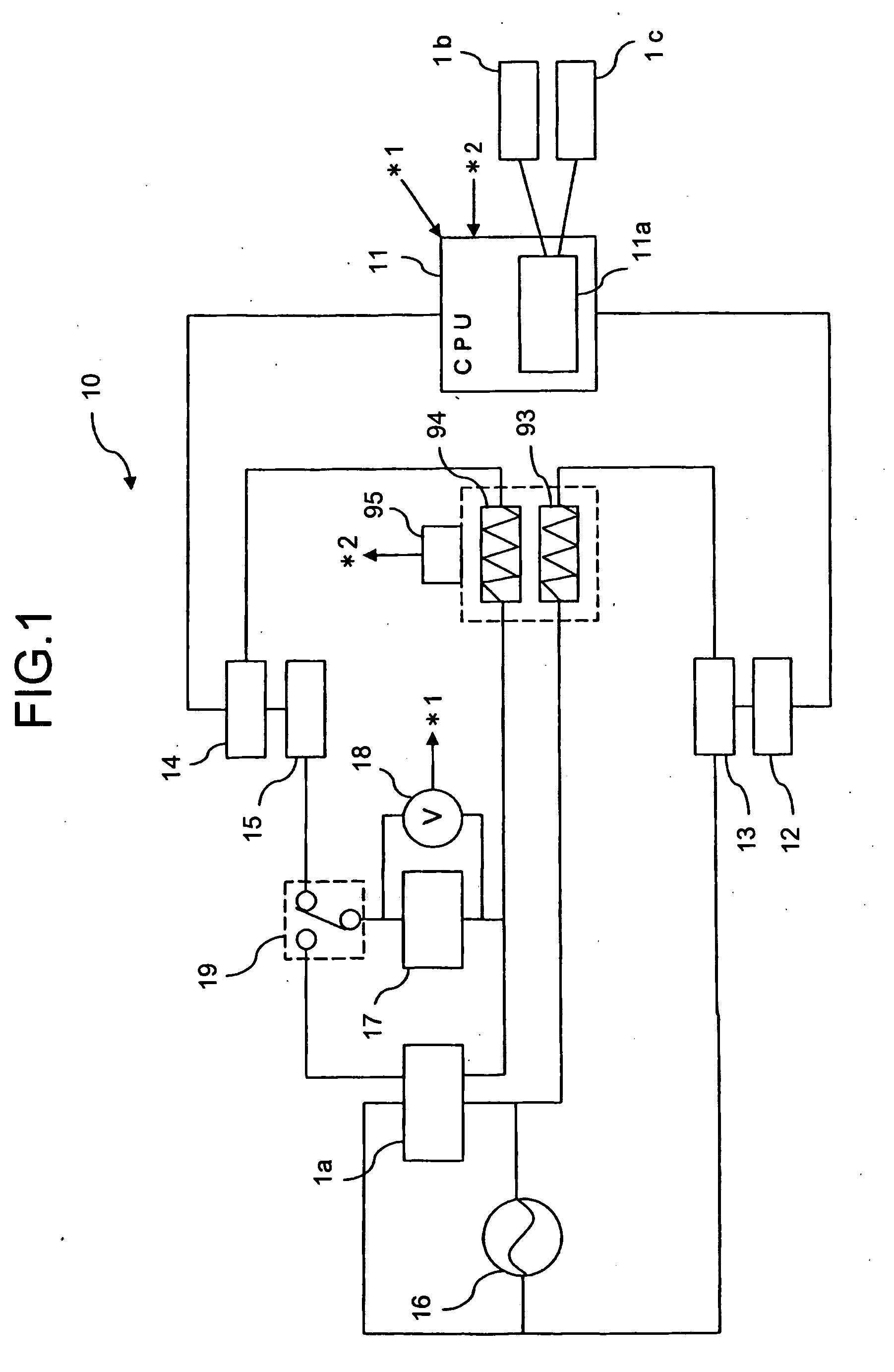
[0022] An example of a fixing unit is illustrated in FIG. 4. The fixing unit shown in FIG. 4 includes a fixing roller (fixing member) 91, a pressurizing roller (fixing member) 92, and a temperature sensor (temperature detecting section) 95. The fixing roller 91 is heated by heaters 93 and 94 in a heating section, and rotates in a clockwise direction. The pressurizing roller 92 is pressed against the fixing roller 91 with a fixed nip pressure and rotates is a counterclockwise direction. The temperature sensor 95 is in contact with the fixing roller 91 and detects a temperature of a surface of the fixing roller 91.

[0023] The fixing roller 91 is normally a hollow cylindrical roller and may also be in the form of an endless belt. The fixing roller 91 is at halt at a time of start-up of the fixing unit and rotates in the c...


PUM


Abstract

A fixing member, a power detector, and a controller are included. The fixing member is heated by a heating unit that generates heat when power is supplied by a commercial power and a capacitor. The power detector detects energy of power stored in the capacitor. The controller performs an identical control to reduce number of copies of an image formed (fixed) per minute (CPM) to a predetermined number (40 CPM) in any of three cases in which the energy is less than a threshold for starting electric discharge when a plurality of recording mediums is continuously passed through the fixing member, in which a cardboard paper is continuously passed, and in which an amount of data of an image to be transferred on the recording medium is large.

Description

CROSS-REFERENCE TO RELATED APPLICATIONS [0001] The present document incorporates by reference the entire contents of Japanese priority document, 2004-029371 filed in Japan on Feb. 5, 2004. BACKGROUND OF THE INVENTION [0002] 1) Field of the Invention [0003] The present invention relates to an image forming apparatus that includes a fixing-unit system with a capacitor that supplies electric power to a heating section. [0004] 2) Description of the Related Art [0005] In copy machines, printers, and facsimiles nowadays, it is a common technique to fix a toner image on a recording medium by heating toner in the toner image with a fixing unit. The toner image is formed by an electrophotography on the recording medium such as a transfer paper, and then, the recording medium is passed through the fixing unit. [0006] In such a fixing unit, a roller or an endless belt is heated by heat from a heating section that is supplied with electric power. A fixing member such as the roller or the endles...

Claims


Application Information

Patent Timeline
IPC IPC(8): G03G15/00G03G15/20G03G21/00G03G21/02
CPCG03G15/5004G03G21/02G03G15/2046G03G2215/00983G03G2215/00556
Inventor MATSUSAKA, SUSUMUKISHI, KAZUHITOKATO, YASUHISAAMITA, AKIYASUOKAMOTO, MASAMITSUKIOKA, YASUTADATAKAGI, HIROMASA
Owner RICOH KK
Why Eureka
Try Eureka