Apparatus and methods for remote installation of devices for reducing drag and vortex induced vibration

a technology of vortex and vibration, which is applied in the direction of manufacturing tools, drilling pipes, and well accessories, etc., can solve the problems of increasing the complexity of the installation

Inactive Publication Date: 2005-08-11
SHELL OIL CO
View PDF87 Cites 16 Cited by
  • Summary
  • Abstract
  • Description
  • Claims
  • Application Information

AI Technical Summary

Problems solved by technology

These vibrations are caused by oscillating dynamic forces on the surface which can cause substantial vibrations of the structure, especially if the forcing frequency is at or near a structural natural frequency.
The vibrations are largest in the transverse (to flow) direction; however, in-line vibrations can also cause stresses which are sometimes larger than those in the transverse direction.
This drilling for and / or producing of hydrocarbons from aquatic, and especially offshore, fields has created many unique engineering challenges.
Further complexities are added when the drilling structure is a floating vessel, as the tensioning apparatus must accommodate considerable heave due to wave action.
It is noted that even moderate velocity currents in flowing fluid environments acting on linear structures can cause stresses.
Accordingly, the adverse effects of drag forces against a riser or other structure caused by strong and shifting currents in these deeper waters increase and set up stresses in the structure which can lead to severe fatigue and / or failure of the structure if left unchecked.
If the frequency of this harmonic load is near the resonant frequency of the structure, large vibrations transverse to the current can occur.
These vibrations can, depending on the stiffness and the strength of the structure and any welds, lead to unacceptably short fatigue lives.
In fact, stresses caused by high current conditions in marine environments have been known to cause structures such as risers to break apart and fall to the ocean floor.
For instance, a riser pipe that is vibrating due to vortex shedding will disrupt the flow of water around it more than a stationary riser.
This results in more energy transfer from the current to the riser, and hence more drag.
The major drawbacks to teardrop shaped fairings is the cost of the fairing and the time required to install such fairings.
Additionally, the critically required rotation of the fairing around the structure is challenged by long-term operation in the undersea environment.
Over time in the harsh marine environment, fairing rotation may either be hindered or stopped altogether.
Anon-rotating fairing subjected to a cross-current may result in vortex shedding that induces greater vibration than the bare structure would incur.
However, strong currents can also occur at great depths causing VIV and drag of risers and other underwater structures at those greater depths.
However, using divers to install VIV and drag reduction equipment at greater depths subjects divers to greater risks and the divers cannot work as long as they can at shallower depths.
Bubbles formed in the blood of a diver who ascends too rapidly cause the diver to experience the debilitating symptoms of the bends.
Likewise, elongated structures with excessive VIV and drag forces that extend far above the ground can be difficult, expensive and dangerous to reach by human workers to install VIV and drag reduction devices.

Method used


Image

  • Apparatus and methods for remote installation of devices for reducing drag and vortex induced vibration
  • Apparatus and methods for remote installation of devices for reducing drag and vortex induced vibration
  • Apparatus and methods for remote installation of devices for reducing drag and vortex induced vibration

Examples


Embodiment Construction

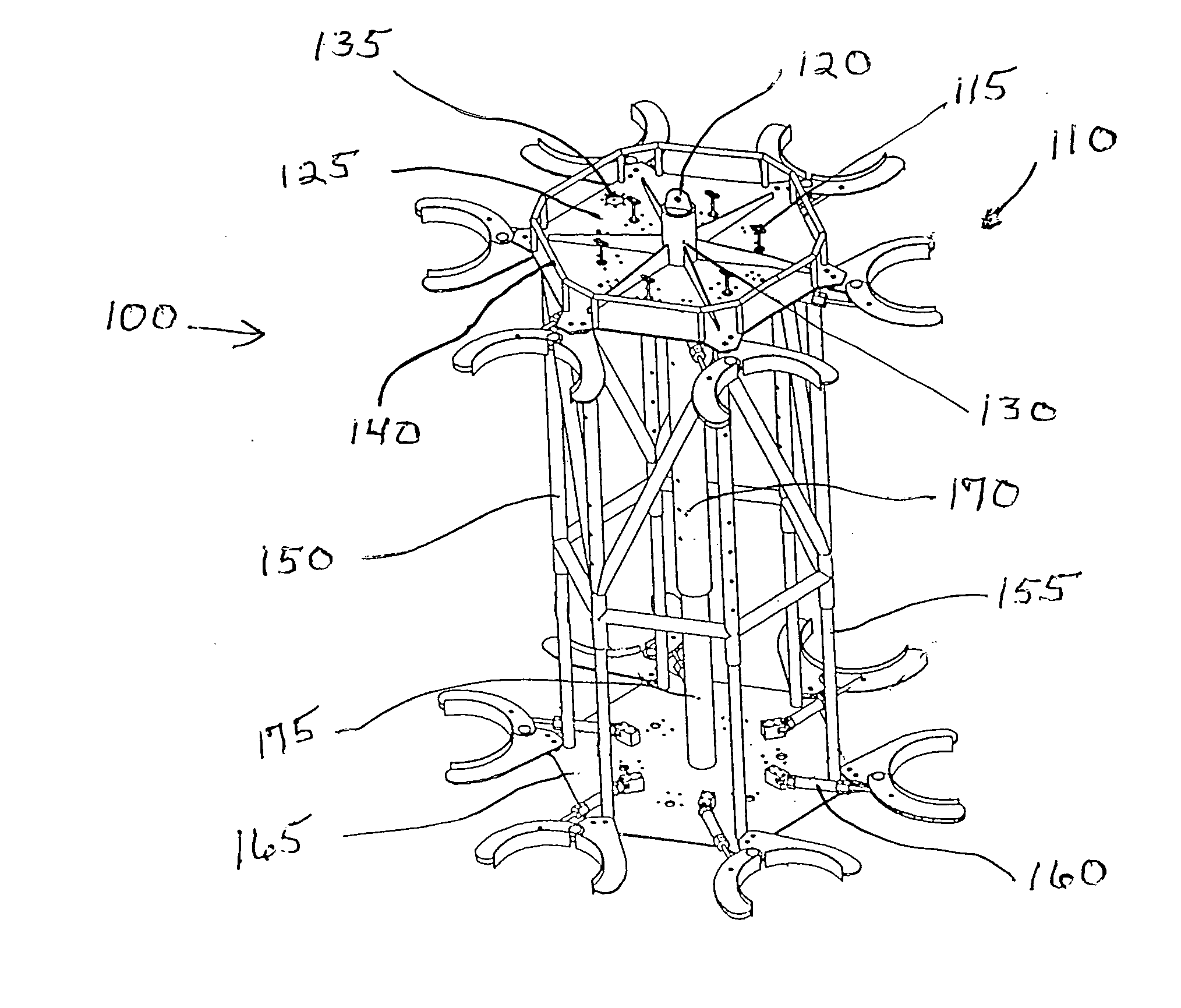
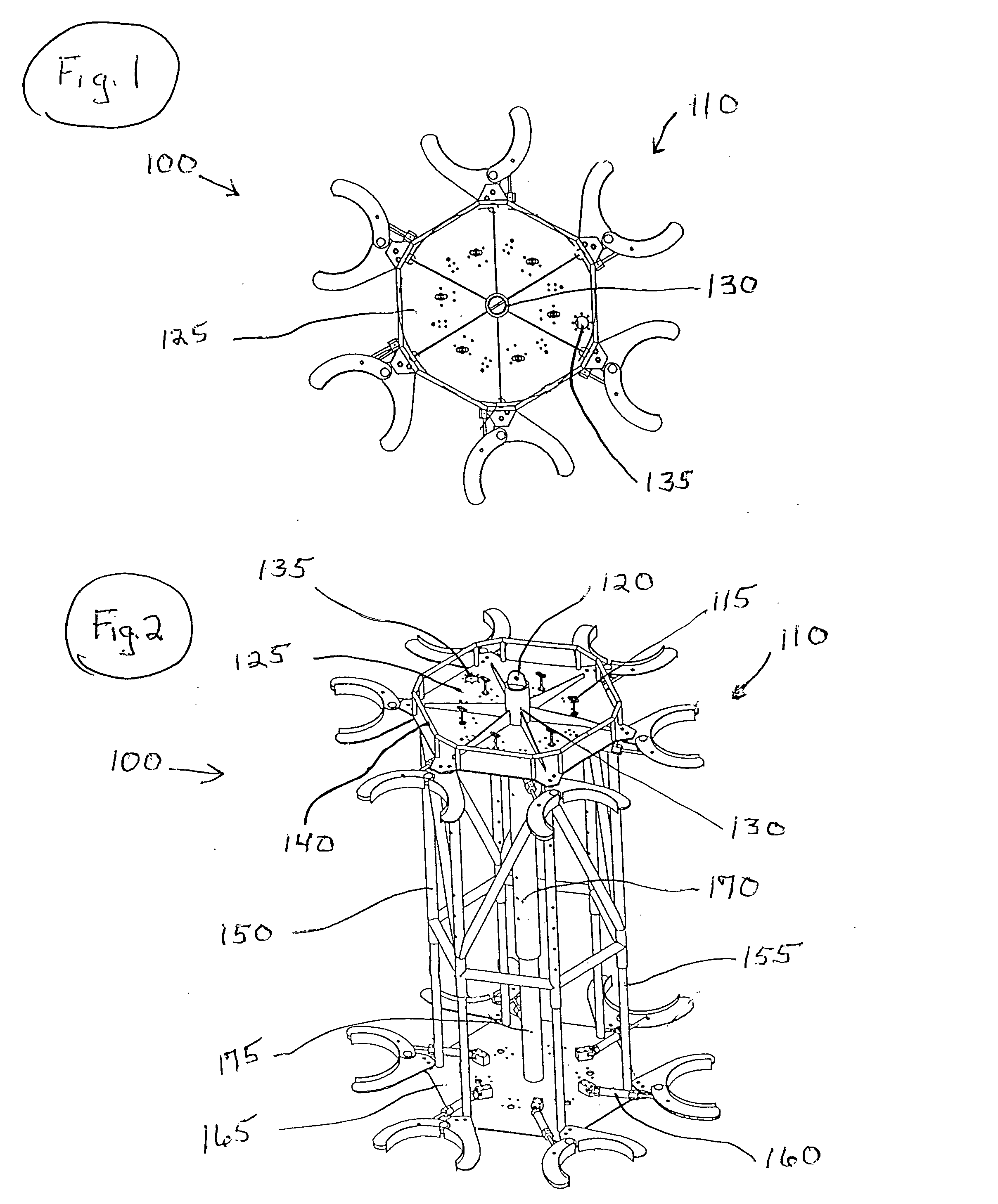
[0054] Referring first to FIG. 1, there is illustrated a top view of Diverless Suppression Deployment Tool (DSDT) 100, which is designed to be remotely operated without the use of human divers in the installation of clamshell-shaped strakes, shrouds, fairings, regular and ultra-smooth sleeves and other VIV and drag reduction equipment underwater to such structures, including but not limited to, oil and gas drilling or production risers, steel catenary risers, and anchor tendons. Slight modifications in DSDT 100 might be required for each particular type of VIV and drag reduction equipment to be installed. These modifications generally will involve modification to clamps 110 so that they can physically accommodate the various types of VIV and drag reduction equipment to be installed.

[0055] For example, the embodiment as shown in FIGS. 1 and 2 is more conducive for the installation of helical strakes.

[0056] Ultra-smooth sleeves are described in U.S. patent application Ser. No. 09 / 62...


PUM

PropertyMeasurementUnit
diameteraaaaaaaaaa
dynamic forcesaaaaaaaaaa
axial tensionaaaaaaaaaa

Abstract

Apparatus and methods for remotely installing vortex-induced vibration (VIV) reduction and drag reduction devices on elongated structures in flowing fluid environments. The apparatus is a tool for transporting and installing the devices. The devices installed can include clamshell-shaped strakes, shrouds, fairings, sleeves and flotation modules.

Description

BACKGROUND OF THE INVENTION [0001] 1. Field of the Invention [0002] The present invention relates to apparatus and methods for remotely installing vortex-induced vibration (VIV) and drag reduction devices on structures in flowing fluid environments. In another aspect, the present invention relates to apparatus and methods for installing VIV and drag reduction devices on underwater structures using equipment that can be remotely operated from above the surface of the water. In even another aspect, the present invention relates to apparatus and methods for remotely installing VIV and drag reduction devices on structures in an atmospheric environment using equipment that can be operated from the surface of the ground. [0003] 2. Description of the Related Art [0004] Whenever a bluff body, such as a cylinder, experiences a current in a flowing fluid environment, it is possible for the body to experience vortex-induced vibrations (VIV). These vibrations are caused by oscillating dynamic f...

Claims


Application Information

Patent Timeline
Patent Type & Authority Applications(United States)
IPC IPC(8): E21B17/01E21B41/04
CPCB63B21/502B63B2021/504E21B17/01Y10T29/49732Y10T29/49895Y10T29/49826E21B41/04
Inventor MCMILLAN, DAVID WAYNEMCDANIEL, RICHARD BRUCE
Owner SHELL OIL CO
Why Eureka
Try Eureka