
Area ruling for vertical stabilizers

a vertical stabilizer and area ruling technology, applied in the direction of fuselage, wing adjustment, transportation and packaging, etc., can solve the problems of jet-powered fighters, limited subsonic flight, and designers who had no idea how to address this problem, so as to reduce the overall change rate of cross-sectional area of aircraft and reduce the wave drag of vehicles or devices.

Inactive Publication Date: 2005-06-02
SUPERSONIC AEROSPACE INT
View PDF18 Cites 13 Cited by
  • Summary
  • Abstract
  • Description
  • Claims
  • Application Information

AI Technical Summary

Benefits of technology

[0011] According to other embodiments, an aircraft design system comprises logic instructions operable to apply area ruling theory to the tail section of the aircraft, including configuring a vertical fin with at least one “waisted” area to minimize the overall rate of change of cross-sectional area of the aircraft.
[0012] In some embodiments, a number of vertical stabilizer configurations can be optimized for minimum drag at different Mach numbers. The configurations can be weighted according to selected criteria, and the average of the weighted configurations can be taken as a final configuration. The weighting factors can be based on any suitable constraint(s) or criteria. For example, for an aircraft, the weighting factors can be based on percent of typical flight profile spent at each Mach number, minimum drag, the difference between thrust available and thrust required (referred to as pinch-point), and / or minimum sonic boom. Applying area ruling to the vertical stabilizer helps to further reduce the wave drag of the vehicle or device to operate efficiently over expected operating conditions, low boom climb and cruise, high speed cruise, and landing of an aircraft.

Problems solved by technology

Since the physics of supersonic flight were still largely a mystery to manufacturers, designers had no idea how to address this problem except to provide their aircraft with more powerful engines.
Even though jet engine technology was rapidly advancing in those days, the first generation of jet-powered fighters was hampered by relatively low-thrust engines which limited them to subsonic flight.
However, initial flight tests of the YF-102 prototype indicated that the aircraft could not reach Mach 1.
It is very difficult, however, to achieve realistic vehicle configurations that completely meet the ideal Sears-Haack body.

Method used


Image

  • Area ruling for vertical stabilizers
  • Area ruling for vertical stabilizers
  • Area ruling for vertical stabilizers

Examples


Embodiment Construction

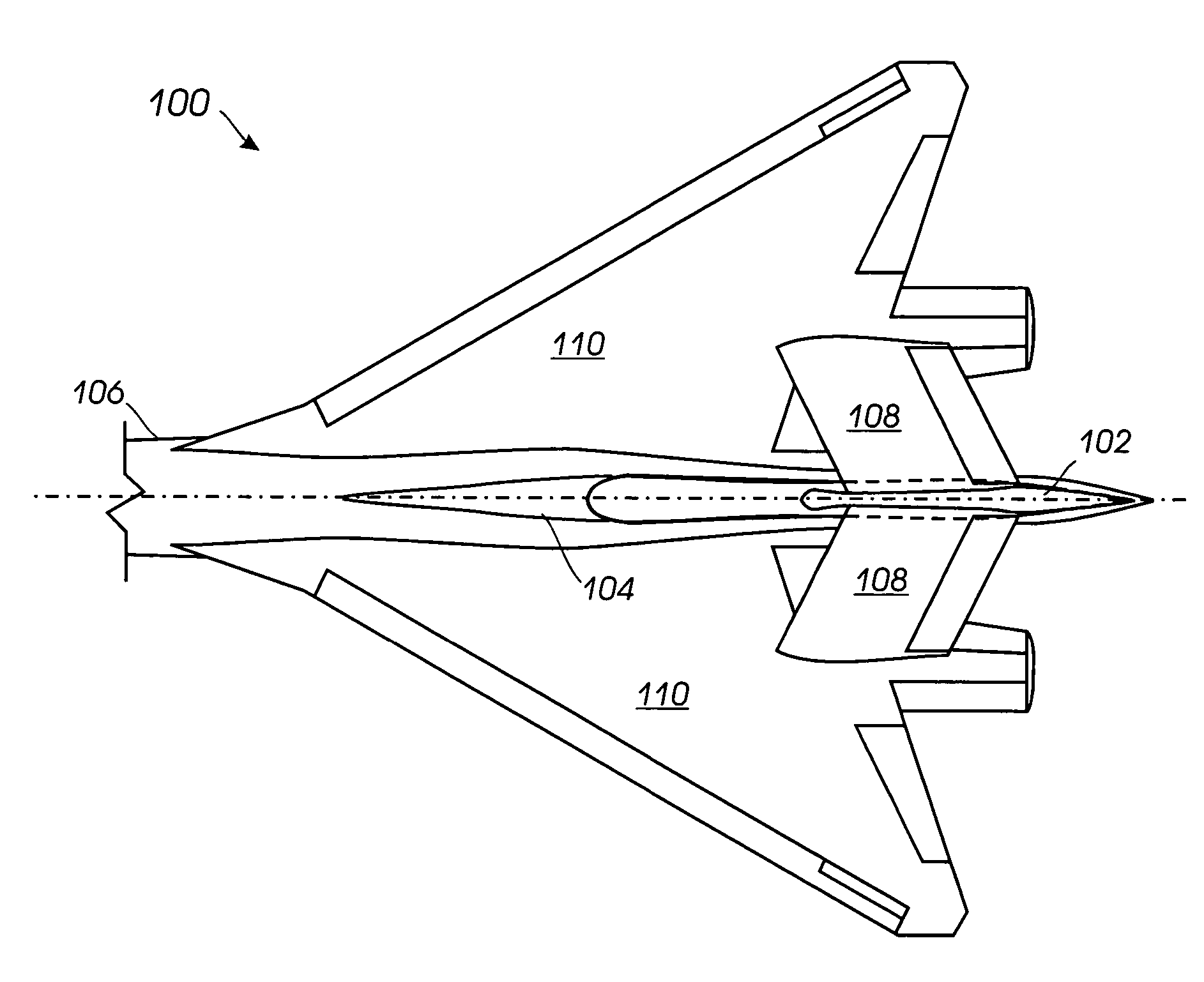
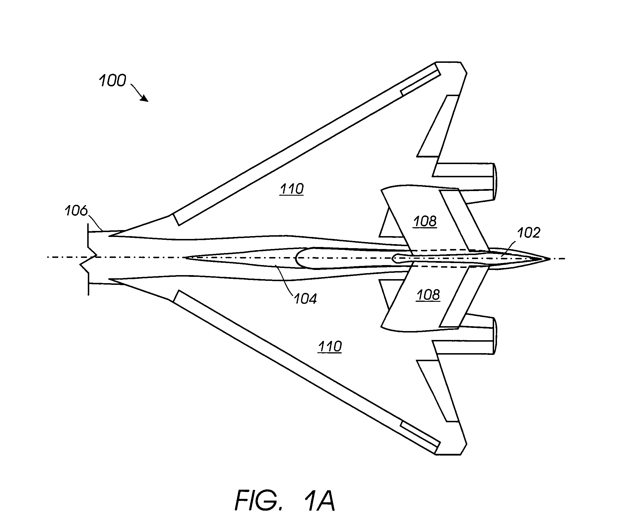
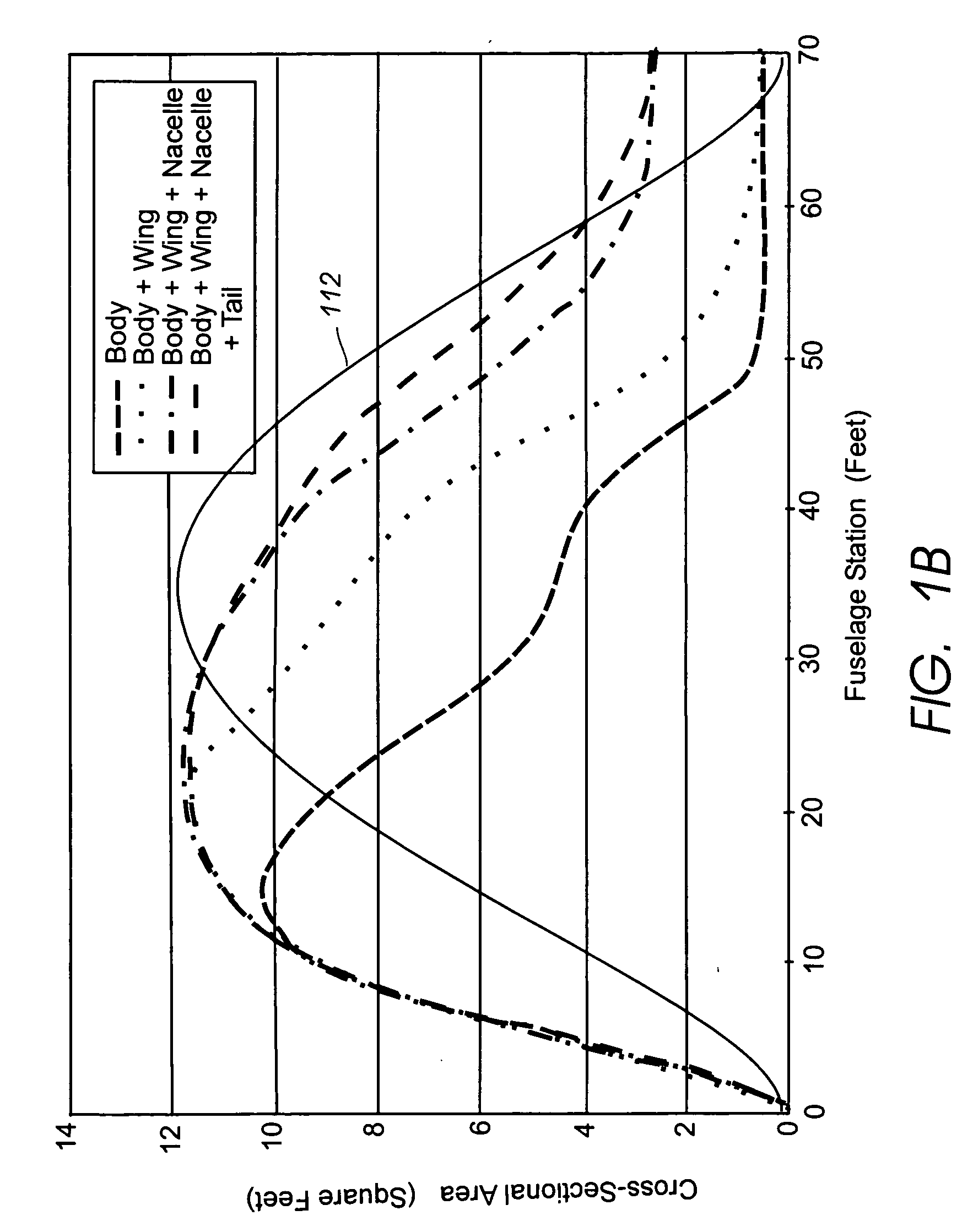
[0024] Referring to FIGS. 1A through 1D, FIG. 1A is a top view of an embodiment of a rear portion of aircraft 100 including vertical fin 102 extending from strake 104, rear fuselage portion 106, inverted V-tail 108, and wings 110. While both the tip and root of vertical fin 102 are shown shaped according to area ruling concepts, in some embodiments, either the tip or root, but not both, of vertical fin 102 can be area ruled. Additionally, the area ruled shape of vertical fin 102 and strake 104 can include more than one “wasp-waist,” or reduced cross-sectional areas. Applying area ruling to aircraft 100, including vertical fin 102 and strake 104, helps reduce wave drag by reducing the rate of change in the aircraft's overall cross-sectional area, and minimizing the maximum cross-sectional area of the aircraft. Additionally, reducing the volume in the fuselage 106 in the vicinity of vertical fin 102, strake 104, inverted V-tail 108, and wings 110 facilitates application of area ruling...


PUM


Abstract

A vertical stabilizer is configured to minimize the rate of change of cross-sectional area of the vehicle or device to which the vertical stabilizer is mounted. One or more “waisted” areas can be included at the tip and / or the root of the vertical stabilizers, as well as over the distance from tip to root of the vertical stabilizer. In some situations, a strake is mounted on the vehicle or device, such as an aircraft, and the vertical stabilizer is mounted to the tip of the strake. The strake can also be area ruled with one or more “waisted” sections at the juncture of the vertical stabilizer. Applying area ruling to the vertical stabilizer helps to further reduce the drag of the vehicle or device.

Description

BACKGROUND OF THE INVENTION [0001] The area rule is an important concept related to the drag on an aircraft or other body in transonic and supersonic flight. The area rule was developed in the early 1950s when production fighter designs began pushing ever closer to the sound barrier. Designers had found that the drag on these aircraft increased substantially when the planes traveled near Mach 1, a phenomenon known as the transonic drag rise. The increase in drag is due to the formation of shock waves over portions of the vehicle, which typically begins around Mach 0.8. The drag increase reaches a maximum near Mach 1. Because the drag results from the shock waves, this type of drag is referred to as wave drag. [0002] Since the physics of supersonic flight were still largely a mystery to manufacturers, designers had no idea how to address this problem except to provide their aircraft with more powerful engines. Even though jet engine technology was rapidly advancing in those days, the...

Claims


Application Information

Patent Timeline
IPC IPC(8): B64C1/38B64C3/38
CPCB64C3/38B64C1/38B63B39/06B64C5/02B64C23/06B63B32/60B64C5/06
Inventor MORGENSTERN, JOHN M.ARSLAN, ALAN E.MOOSE, GARRET M.
Owner SUPERSONIC AEROSPACE INT
Learn More