Optical disk recording method employing a plurality of recording areas and apparatus therefor

a technology of optical disk and recording area, which is applied in the direction of digital signal error detection/correction, instruments, recording signal processing, etc., can solve the problems of large amount of power consumption, difficult to reduce the size of the apparatus, and excessive access time, so as to minimize the rotational speed change and reduce the rate of motor spindle rotation. , the effect of reducing power consumption

Inactive Publication Date: 2005-02-15
PANASONIC CORP
View PDF15 Cites 0 Cited by
  • Summary
  • Abstract
  • Description
  • Claims
  • Application Information

AI Technical Summary

Benefits of technology

To achieve the above object, the disk apparatus according to the present invention comprises a broadband synchronizing clock generator and a disk rotation controller which controls the disk rotation according to the reproducing position of the disk, more specifically, controls the rotating velocity at constant angular velocity (CAV) using the current rotating velocity in a pull-in enable range of the synchronizing clock generator and, on the other hand, at constant linear velocity (CLV) to minimize rotating-speed changes, which allow the reproduced signal to be pulled into synchronism, smaller than the rotating velocity used heretofore in a range exceeding the pull-in enable range.
Under this arrangement, when data is reproduced on the optical disk, even if the reproducing position on the optical disk changes, the rate of change of the number of motor spindle revolutions can be minimized, and therefore the spindle motor can be driven with low power consumption and access time can be reduced.
In addition to the above-mentioned components, the disk apparatus according to the present invention further comprises a selector to switch over the control circuits for CAV control and CLV control, and recording area dividing means for controlling the subdivided areas, whereby data is accessed by switching over CAV control and CLV control, and in CAV control, the subdivided areas and the number of divisions are made variable to make possible low power consumption and high-speed access.

Problems solved by technology

(1) Since the linear velocity must be made constant, when the reproducing position of the optical pickup varies as in a seek, a considerable delay occurs until the rotating velocity of the spindle motor varies to follow the changes of the pickup position, with the result that access time has to be excessively long.
(2) In order to quickly vary the rotation of the spindle motor, a large torque is required, so that a large amount of power is consumed, heat is generated in the spindle motor and it is difficult to reduce the size of the apparatus.
Nevertheless, because the rotating velocity of the spindle motor increases as the data transfer rate is increased, the above-mentioned problem has yet to be solved drastically.

Method used


Image

  • Optical disk recording method employing a plurality of recording areas and apparatus therefor
  • Optical disk recording method employing a plurality of recording areas and apparatus therefor
  • Optical disk recording method employing a plurality of recording areas and apparatus therefor

Examples


embodiment 1

(Embodiment 1)

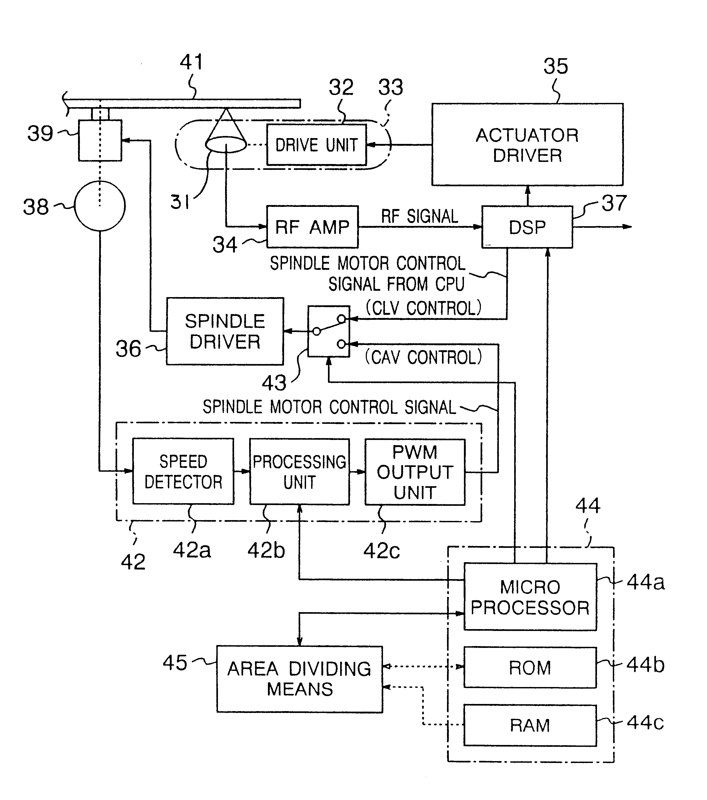
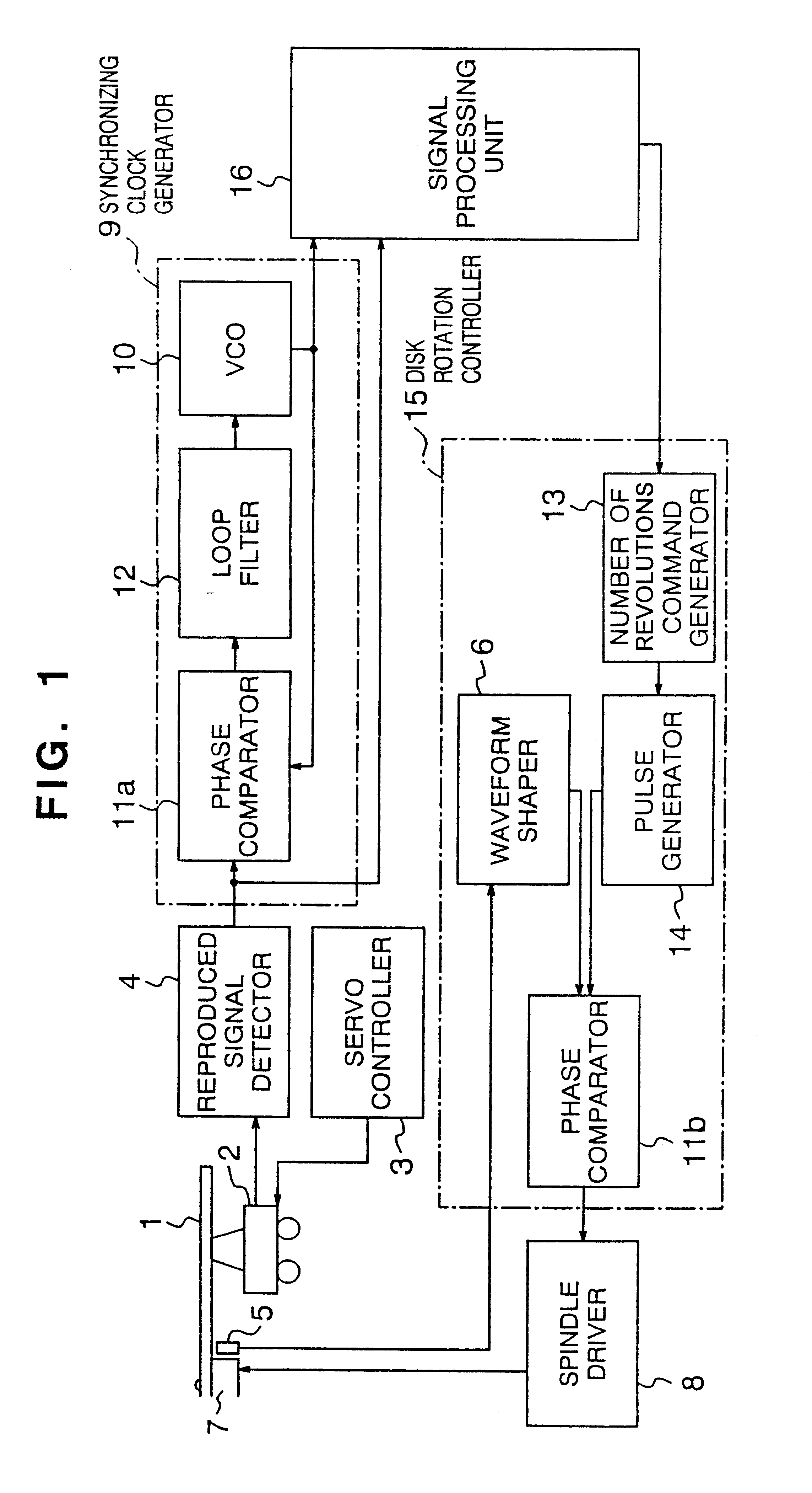
Referring to the accompanying drawings, a first embodiment of the present invention will be described. FIG. 1 is a block diagram of the optical disk apparatus according to a first embodiment of the present invention. Reference numeral 1 denotes an optical disk on which data has been recorded at constant linear velocity (CLV), 2 denotes a servo controller for causing the optical pickup 2 to follow the runout and eccentricity of the optical disk 1, 4 denotes a reproduced signal detector for digitizing the signal reproduced from the pickup 2, 7 denotes a spindle motor which rotates with an optical disk mounted thereon, 5 denotes an encoder for generating an analog rotation signal in accordance with the motor spindle rotation, 6 denotes a waveform shaper for digitizing the analog rotation signal, 13 denotes a number of revolutions command generator (corresponding to a processor such as a CPU) for calculating a number of revolutions according to the reproducing position on ...

embodiment 2

(Embodiment 2)

A second embodiment of the present invention will be described with reference to the accompanying drawings. FIG. 3 is a block diagram of the optical disk apparatus according to a second embodiment of the present invention. In FIG. 3, reference numeral 1 denotes an optical disk, 2 denotes an optical pickup, 3 denotes a servo controller, 4 denotes a reproduced signal detector, 7 denotes a spindle motor, 5 denotes an encoder, 6 denotes a waveform shaper, 13 denotes a number of revolutions command generator, 14 denotes a pulse generator, 11a and 11b denotes phase comparators, 8 denotes a spindle driver, 10 denotes VCO, 12 denotes a loop filter, 16 denotes a signal processor, 9 denotes a synchronizing clock generator, and 15 denotes a disk rotation controller. Those components, being the same as in the first embodiment, are designated by the same reference numerals and their descriptions are omitted. Reference numeral 17 denotes an access controller for controlling an acces...

embodiment 3

(Embodiment 3)

A third embodiment of the present invention will be described with reference to the accompanying drawings. FIG. 5 is a block diagram of the optical disk apparatus in the third embodiment of the present invention. In FIG. 5, reference numeral 1 denotes an optical disk, 2 denotes an optical pickup, 3 denotes a servo controller, 4 denotes a reproduced signal detector, 7 denotes a spindle motor, 5 denotes an encoder, 6 denotes a waveform shaper, 13 denotes a number of revolutions command generator, 14 denotes a pulse generator, 11a and 11b denote phase comparators, 8 denotes a spindle driver, 10 denotes VCO, 12 denotes a loop filter, 16 denotes a signal processor, 9 denotes a synchronizing clock generator, and 15 denotes a disk rotation controller. Those components, being the same as in the first embodiment, are designated by the same reference numerals and their descriptions are omitted. Reference numeral 18 denotes a linear velocity detector for detecting the linear velo...


PUM

PropertyMeasurementUnit
linear velocityaaaaaaaaaa
rotating velocityaaaaaaaaaa

Abstract

An optical disk apparatus comprising a reproduced signal detector which digitizes a reproduced signal from an optical disk, a broadband synchronizing clock signal generator for generating a synchronizing clock signal for use in reproducing data, a signal processor for processing signals, and a disk rotation controller for controlling the optical disk by switching control modes according to the reproducing position of the disk, that is, performing CAV control using the constant rotating velocity which is the same as the current rotating velocity in a range where the synchronizing clock signal generator allows a reproduced signal to be subjected to pull-in-synchronization, and performing CLV control so that the linear velocity is constant to minimize the pull-in-enable changes of number of revolutions in a range exceeding the pull-in-synchronization range, by which arrangement the amount of change of number of spindle motor revolutions when the reproducing position of the optical pickup changes is minimized, thus further reducing power consumption and access time. The optical disk apparatus comprises a selector to switch over the control systems, and area dividing means to manage the divided areas, and while switching over CAV control and CLV control, records data, and varies the divided areas or the number of divided areas in CAV control according to recording capacities, so that lower power consumption and higher-speed access can be realized.

Description

BACKGROUND OF THE INVENTIONThe present invention relates to an optical disk apparatus which serves as an external memory unit or a data file for a computer to record and reproduce a large quantity of data at high speed.Research and development are currently under way to seek wider applications and higher performance with regard to optical disks. Optical disks constitute a recording medium with a high recording density and hence with a very large storage capacity. As an example of its application, CD-ROM drive units are finding wide acceptance for use in computers to reproduce data.The CD-ROM drive unit is an application of the music-playback compact disk (CD) for use as a read-only memory. Operated under the system for reproducing data at a constant linear velocity (CLV), the 12-cm-diameter optical disk is used as a recording medium with a large memory capacity of about 600M bytes. In addition to the read-only CD-ROM, other products emerging from the research and development efforts...

Claims


Application Information

Patent Timeline
Patent Type & Authority Patents(United States)
IPC IPC(8): G11B19/26G11B20/10G11B19/28G11B19/00G11B7/007G11B20/14G11B20/12G11B7/0037G11B7/00G11B7/085G11B19/02G11B19/12G11B19/247
CPCG11B7/0037G11B7/007G11B7/0079G11B19/00G11B19/26G11B19/28G11B20/10G11B20/1258G11B20/1403G11B2020/10981
Inventor KUSANO, TAIZOUKASHIWABARA, YOSHIROWADA, YASUHIROUMEDA, KEISUKE
Owner PANASONIC CORP
Why Eureka
Try Eureka