
Thin film transistor, method for manufacturing the thin film transistor and display device comprising the thin film transistor

a thin film transistor and transistor technology, applied in transistors, semiconductor devices, electrical appliances, etc., can solve the problems of amorphous silicon thin film transistors, and increased manufacturing costs

Pending Publication Date: 2022-06-30
LG DISPLAY CO LTD
View PDF0 Cites 0 Cited by
  • Summary
  • Abstract
  • Description
  • Claims
  • Application Information

AI Technical Summary

Benefits of technology

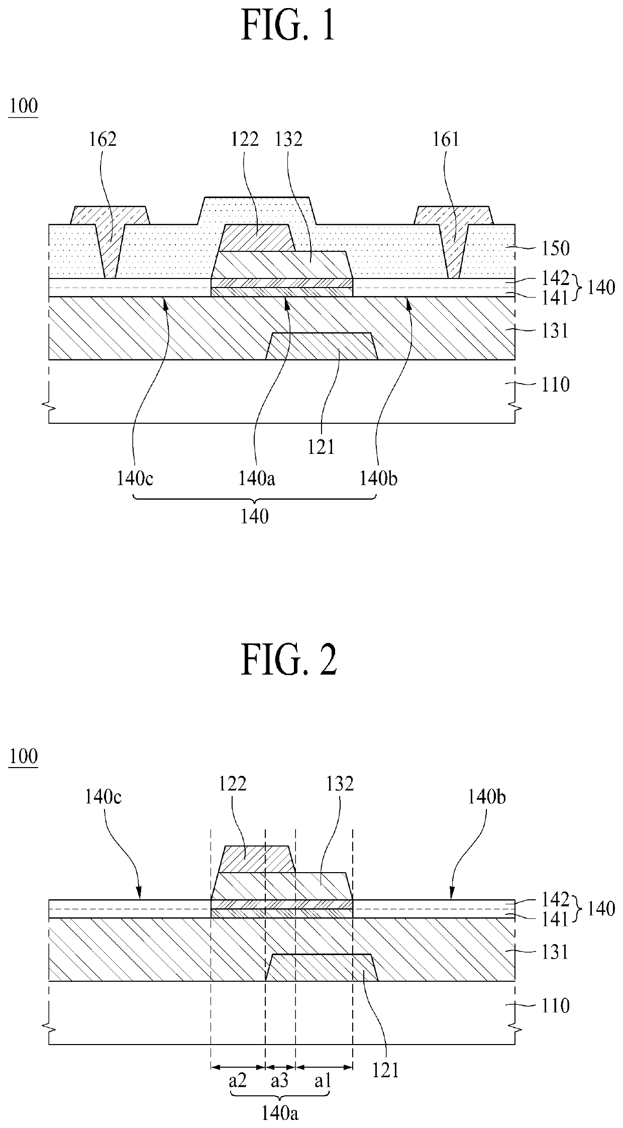
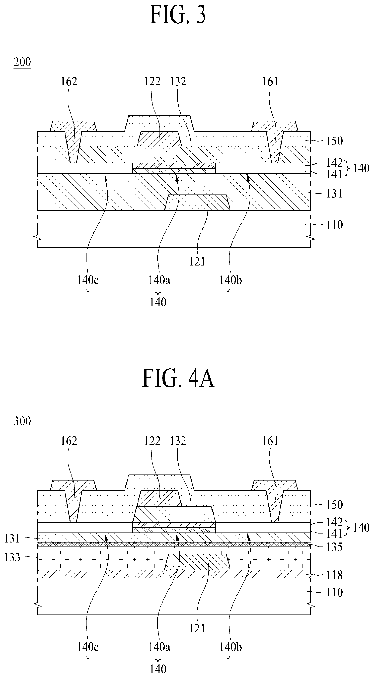
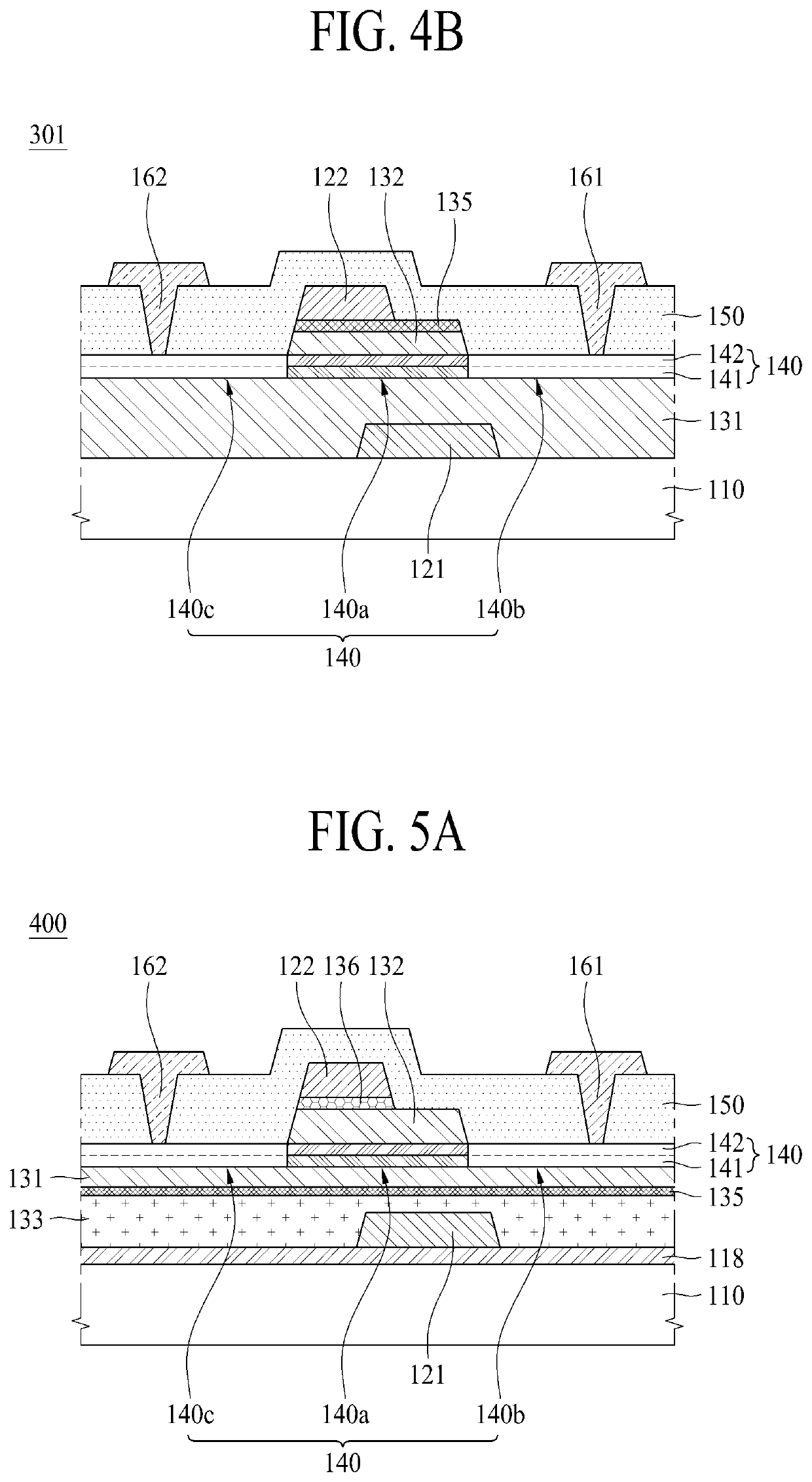
The present disclosure aims to provide a thin film transistor with properties of both top gate and bottom gate structures to minimize changes in threshold voltage. Additionally, the transistor has improved driving stability due to the presence of portions affected by both top and bottom gates in one channel portion. Furthermore, the transistor has improved driving stability as a portion for moving the threshold voltage to a positive direction and a portion for moving it to a negative direction are connected in series in one channel portion. Finally, the transistor can minimize changes in threshold voltage by inducing movement of the threshold voltage to a positive direction by electron trap in an excess oxygen area and inducing movement of it to a negative direction by hole trap in an excess hydrogen area.

Problems solved by technology

On the other hand, the amorphous silicon thin film transistor can have a drawback in that the amorphous silicon thin film transistor is restrictively used for an active matrix organic light emitting diode (AMOLED) because a current driving capacity can have some undesirable traits of low mobility and there is a change in a threshold voltage.
However, since a process of manufacturing the polycrystalline silicon thin film transistor uses a step of crystallizing the amorphous silicon, a manufacturing cost can be increased due to the increased number of the process steps and crystallization is needed at a high temperature.
Therefore, it may be difficult to apply the polycrystalline silicon thin film transistor to a large-sized display device.
Also, it may be difficult to ensure uniformity of the polycrystalline silicon thin film transistors due to polycrystalline properties.
However, the oxide semiconductor thin film transistor can have issues regarding stability and electron mobility may deteriorate as compared with the polycrystalline silicon thin film transistor.
Due to this change in the driving characters of the TFT, the life of the device may be shortened, image quality can degrade, and costly compensation techniques and additional circuitry may be needed.

Method used


Image

  • Thin film transistor, method for manufacturing the thin film transistor and display device comprising the thin film transistor
  • Thin film transistor, method for manufacturing the thin film transistor and display device comprising the thin film transistor
  • Thin film transistor, method for manufacturing the thin film transistor and display device comprising the thin film transistor

Examples


Embodiment Construction

[0059]Advantages and features of the present disclosure, and implementation methods thereof will be clarified through following embodiments described with reference to the accompanying drawings. The present disclosure may, however, be embodied in different forms and should not be construed as limited to the embodiments set forth herein. Rather, these embodiments are provided so that this disclosure will be thorough and complete, and will fully convey the scope of the present disclosure to those skilled in the art. Further, the present disclosure is only defined by scopes of claims.

[0060]A shape, a size, a ratio, an angle, and a number disclosed in the drawings for describing embodiments of the present disclosure are merely an example, and thus, the present disclosure is not limited to the illustrated details. Like reference numerals refer to like elements throughout the specification. In the following description, when the detailed description of the relevant known function or confi...


PUM


Abstract

A thin film transistor can include a first gate electrode, an active layer including a channel portion, and a second gate electrode. The active layer is between the first gate electrode and the second gate electrode, and at least a portion of the first gate electrode does not overlap with the second gate electrode. Further, at least a portion of the second gate electrode does not overlap with the first gate electrode, and the channel portion overlaps with at least one of the first gate electrode and the second gate electrode. In addition, a first portion of the channel portion can overlaps with one of the first gate electrode and the second gate electrode, and a second portion of the channel portion can overlap with a remaining one of the first gate electrode and the second gate electrode that is not overlapped by the first portion of the channel portion.

Description

CROSS-REFERENCE TO RELATED APPLICATIONS[0001]This application claims priority to Korean Patent Application No. 10-2020-0186700 filed in the Republic of Korea on Dec. 29, 2020, and Korean Patent Application No. 10-2021-0175278 filed in the Republic of Korea on Dec. 9, 2021, the entire contents of all these applications being hereby incorporated by reference as if fully set forth herein into the present application.BACKGROUNDField of the Invention[0002]The present disclosure relates to a thin film transistor, a method for manufacturing the thin film transistor, and a display device comprising the thin film transistor.Discussion of the Related Art[0003]Since a thin film transistor can be manufactured on a glass substrate or a plastic substrate, the thin film transistor has been widely used as a switching element or a driving element of a display device, such as a liquid crystal display device or an organic light emitting device.[0004]The thin film transistor can be categorized into an ...

Claims


Application Information

Patent Timeline
IPC IPC(8): H01L29/786H01L29/66
CPCH01L29/78648H01L29/7869H01L29/4908H01L29/78696H01L29/66969H01L21/34H01L27/1225H01L27/1229
Inventor BAECK, JUHEYUCKLEE, DOHYUNGJEONG, CHANYONG
Owner LG DISPLAY CO LTD
Learn More