
Separable blade for wind turbine

a technology of wind turbines and blades, which is applied in the installation of lighting conductors, marine propulsion, vessel construction, etc., can solve the problems of blade breaking and the emerging problem of wind turbine blade transportation

Active Publication Date: 2005-08-11
HITACHI LTD
View PDF3 Cites 12 Cited by
  • Summary
  • Abstract
  • Description
  • Claims
  • Application Information

AI Technical Summary

Benefits of technology

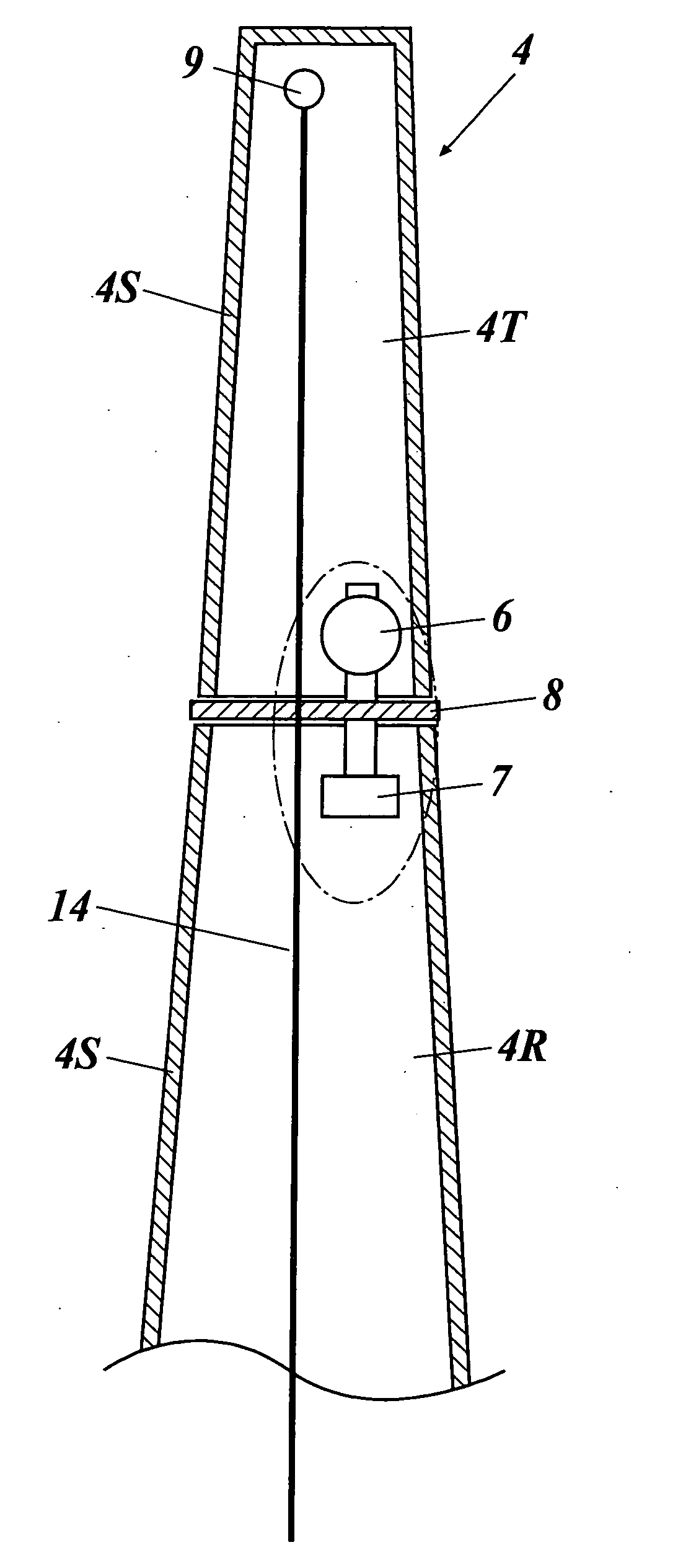
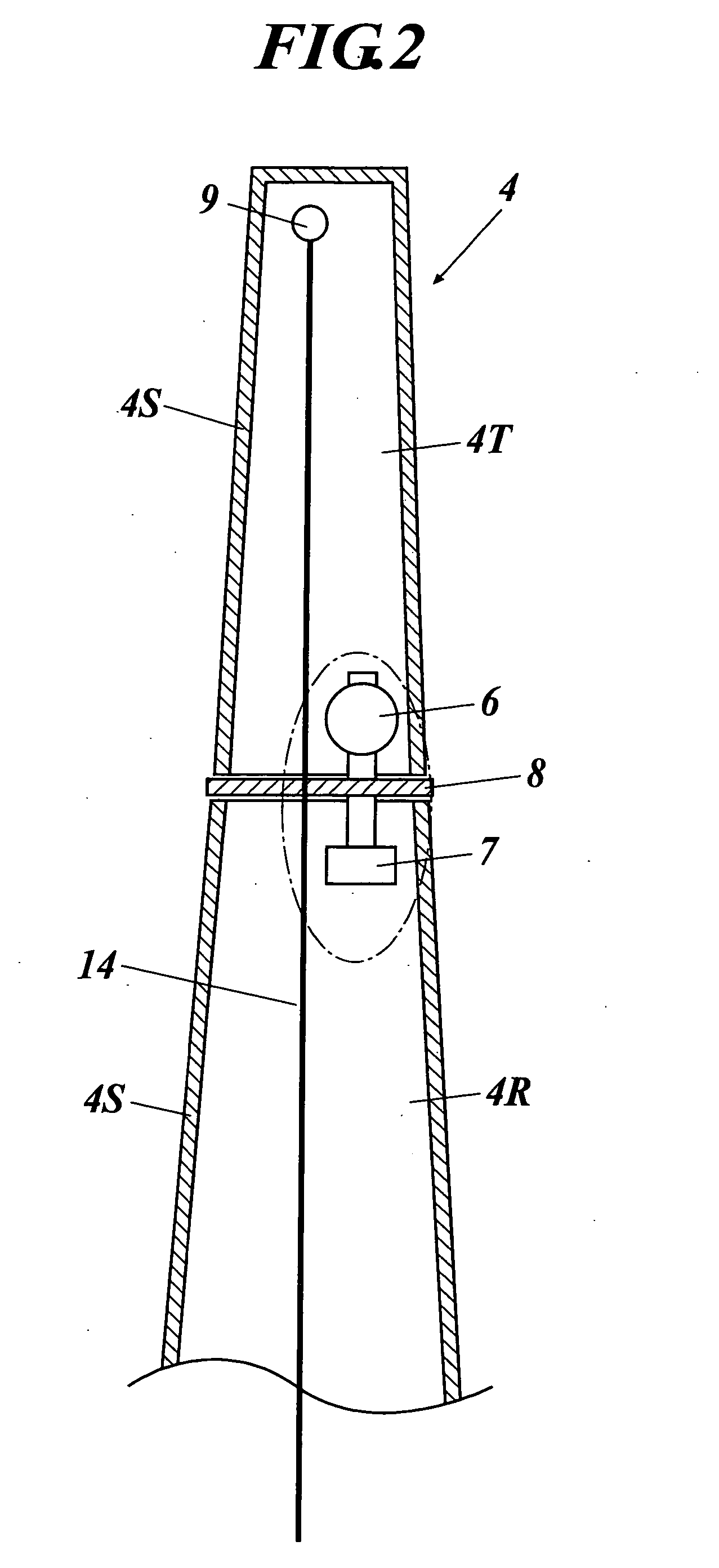
The present invention relates to a wind turbine blade design that can protect against lightning strike. The blade is divided into inner and outer blade portions and a joining member is used to connect the two parts. A metal plate is placed between the inner and outer blade portions and is electrically connected to the joining member. An in-blade electrical conduction wire extends from the metal plate through the blade root part to outside of the blade. The metal plate has a flat shape that matches the shape of the blade's junction part. The technical effect of this design is to prevent breakage of the blade caused by lightning strike and to guide the lightning current to the outside of the blade.

Problems solved by technology

Meanwhile, in conjunction with a request of large-sizing a wind turbine these days, there is an emerging problem in transportation of wind turbine blades.
However, if such a separable blade is adopted, there is a new emerging problem that the blade can be broken when lightning strikes the above-described joining member made of metal.

Method used


Image

  • Separable blade for wind turbine
  • Separable blade for wind turbine
  • Separable blade for wind turbine

Examples


Embodiment Construction

[0024] Hereinafter, an embodiment of the present invention will be described with reference to drawings.

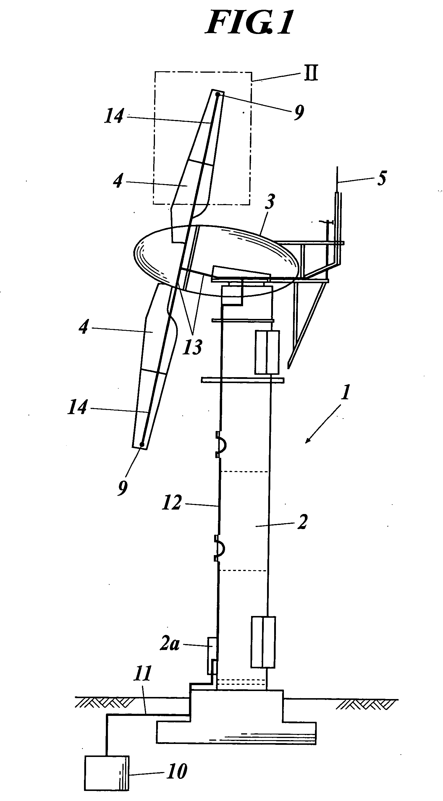
[0025] First, with reference to FIG. 1 and FIG. 2, a horizontal axis wind turbine 1 comprising a separable blade4 regarding the present embodiment will be described.

[0026] As shown in FIG. 1, the horizontal axis wind turbine 1 comprises a tower 2 set on the ground, a nacelle 3 attached to a top part of the tower 2, two pieces of separable blades 4 attached to a main shaft located inside (illustration omitted) of the nacelle 3, and the like.

[0027] In the vicinity of a setting location of the tower 2, into the ground, a ground metal plate 10 lays underground as shown in FIG. 1, and a ground lightning conduction wire 11 is placed between the ground metal plate 10 and a ground terminal 2a of the tower 2. Further, in the tower 2, as shown in FIG. 1, an in-tower lightning conduction wire 12 is placed. A bottom of the in-tower lightning conduction wire 12 is connected to the ground te...


PUM


Abstract

A separable blade for a wind turbine, the separable blade being divided at a center part thereof in a longitudinal direction into an inner blade portion corresponding to a blade root side and an outer blade portion corresponding to a blade end portion, wherein the separable blade is structured by joining the inner blade portion and the outer blade portion with a joining member made of metal, the separable blade includes: a metal plate placed between the inner blade portion and the outer blade portion and electrically connected to the joining member; and an in-blade electrical conduction wire arranged to extend from the metal plate through a blade root part of the inner blade portion to outside of the blade.

Description

CROSS-REFERENCE TO RELATED APPLICATION [0001] This application claims priority to Japanese Patent Application No. 2004-29234 filed on Feb. 5, 2004, which is incorporated herein by reference in its entirety. BACKGROUND OF THE INVENTION [0002] 1. Field of the Invention [0003] The present invention relates to a separable blade for a wind turbine with a lightning protection device. [0004] 2. Description of Related Art [0005] These days, a wind turbine is in practical use. In recent years, in consideration of increasing cases of installing wind turbines at a mountainous area or the like, various proposals have been made for protecting a blade of a wind turbine from lightning. [0006] What is proposed as one example is a technology in which a lightning receptor is placed at an edge part of a blade of a wind turbine, and an electrical conduction wire which extends from the lightning receiving unit up to the edge part of the blade is placed within the blade or on the blade surface, so that t...

Claims


Application Information

Patent Timeline
Patent Type & Authority Applications(United States)
IPC IPC(8): F03D11/00B25F3/00F03D1/00F03D1/06H02G13/00
CPCF03D1/001F03D1/0633F03D1/0675F03D11/00Y02E10/728F05B2240/302F05B2260/02Y02E10/721Y02E10/722F03D11/0033F03D13/10F03D80/00F03D80/30Y02E10/72
Inventor YOSHIDA, SHIGEO
Owner HITACHI LTD
Learn More