Hot foil stamping or printing device for transferring surface portions onto a flat material

a technology of surface portions and printing devices, which is applied in the direction of embossing decorations, lamination, decorative arts, etc., can solve the problems of increased adjustment difficulty, difficulty in adapting to operating conditions, and again arising disadvantages of adjustment, so as to improve the grip mechanism of the sheet, direct and precise adjustment of the printing gap, and substantial clearance freedom of the printing cylinder

Inactive Publication Date: 2005-08-18
STEUER PRINTING TECH
View PDF5 Cites 8 Cited by
  • Summary
  • Abstract
  • Description
  • Claims
  • Application Information

AI Technical Summary

Benefits of technology

[0004] Thus, the object of the invention is to provide an applying, printing, particularly a hot foil stamping device with an improved sheet g...

Problems solved by technology

However, such bearers are difficult to adapt to the operating conditions and are consequently unsuitable for hot foil stamping mechanisms where, apart from mechanical influences, there are precise working gaps for obtaining optimum pressure ratios and an i...

Method used


Image

  • Hot foil stamping or printing device for transferring surface portions onto a flat material
  • Hot foil stamping or printing device for transferring surface portions onto a flat material
  • Hot foil stamping or printing device for transferring surface portions onto a flat material

Examples


Embodiment Construction

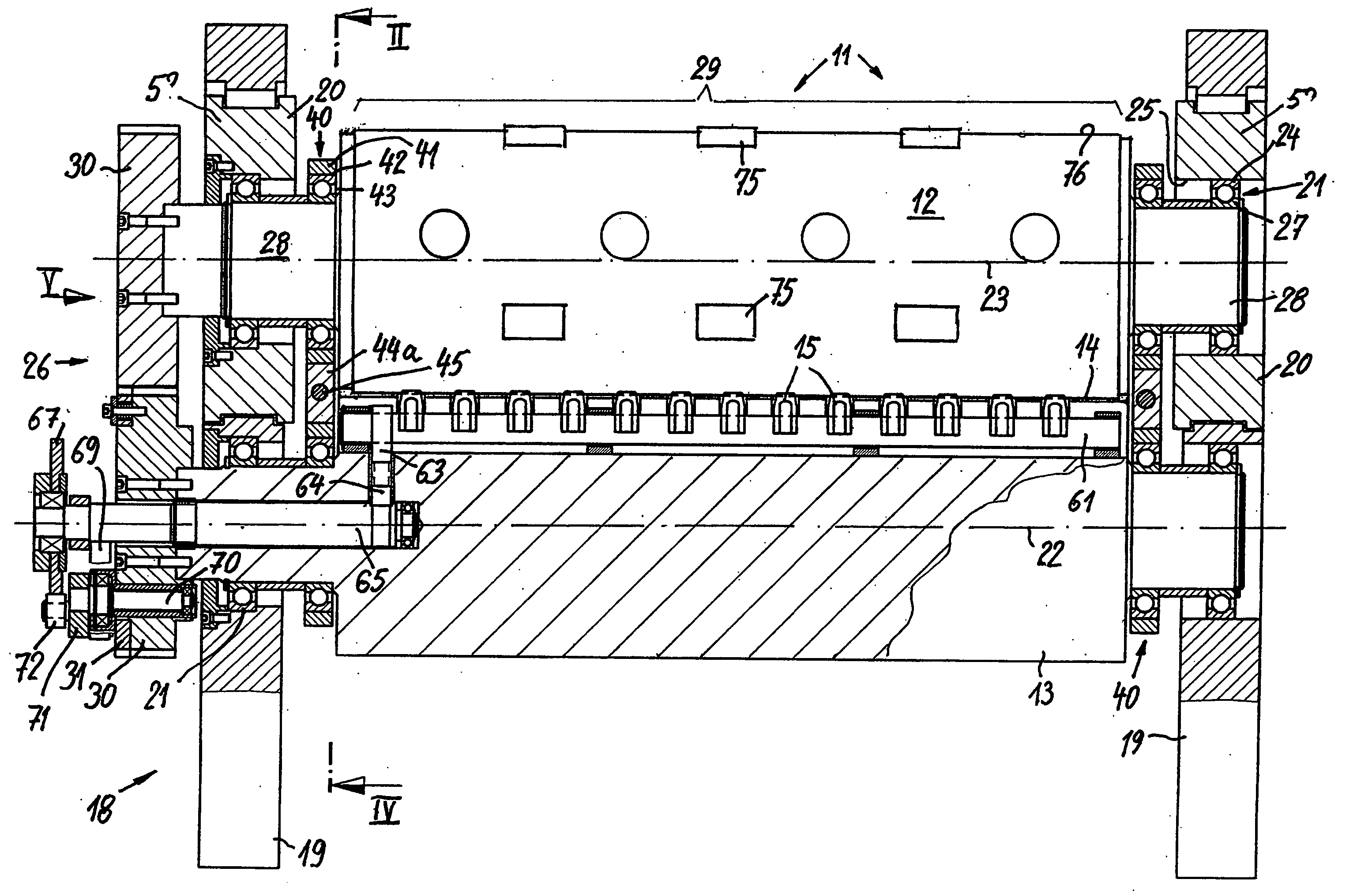
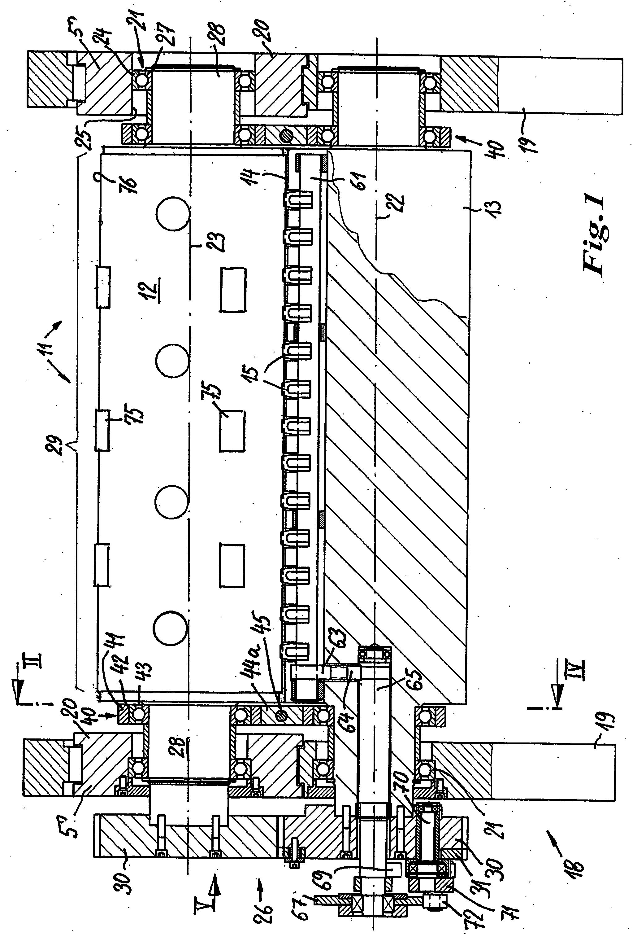
[0018]FIG. 1 shows an hot foil stamping mechanism 11 of an otherwise not shown hot foil stamping machine. It has two cylinders 12, 13, whereof the upper cylinder 12 is the hot foil stamping cylinder and they can be applied to not shown hot foil stamping dies. They serve to transfer surface portions of a film web 16 onto a flat material 17 and they are moved in superimposed manner through a working gap 14 formed between the cylinders 12, 13 (cf. FIG. 5). In the embodiment shown the flat material is formed by individual sheets of paper or similar flat materials, whose leading edge is engaged or grasped by grippers 15 and which are placed around the cylinder circumference. The flat material and film web are conveyed at the same speed as the two cylinders, drive synchronously in opposition, through the working gap 14, projections of a printing block 76 tightly spread over the cylinder 12 pressing the hot foil stamping dies 75 onto the back of the film web and emboss on the latter surfac...


PUM

PropertyMeasurementUnit
Angleaaaaaaaaaa

Abstract

The hot foil stamping mechanism (11) is used for the transfer of surface portions, such as holograms, etc., onto a flat material (1) in the form of a continuous web or sheet. The hot foil stamping mechanism (11) operating in rotary manner has two cooperating cylinders forming a working gap (14) between them. For maintaining constant and precisely adjusting the working gap (14) adjusting means (40) are provided, which have an adjustable adjusting element (44a-c) engaging between the cylinders (12, 13) and acting on the latter by means of running elements (41, 50). The running elements run on the cylinder. The adjusting means can be anti-friction bearings located on the cylinder journal (28). An adjusting element in the form of a wedge or the like supports the outer ring bearings against one another and consequently maintains a constant cylinder spacing.

Description

FIELD OF APPLICATION AND PRIOR ART [0001] The invention relates to an device for surface portions to a flat material by transferring, printing or hot foil stamping having an applying mechanism. Such devices are used for printing, particularly for applying coatings, e.g. metal coatings, holograms or the like present on a film web and usually having a heat seal coating or pressure-activatable coating, to a flat material, i.e. either a sheet or a continuous material web. The surface portions can be already prepared objects, e.g. holograms, or can be structured from a continuous coating by an hot foil stamping tool or die and its hot foil stamping plate, e.g. in the form of a metallized strip. Such objects are increasingly applied to security, currency and advertising materials, e.g. banknotes, entry tickets, packs, etc. [0002] In the case of sheet-fed presses, in which in one of the cylinders is fixed a sheet partly surrounding the cylinder, on the counterpressure cylinder are provided...

Claims


Application Information

Patent Timeline
IPC IPC(8): B41F19/06B41F21/00B41F21/10B44B5/00
CPCY10T156/1741B41F19/062
Inventor STEUER, ARMINSCHOELLHORN, PATRICK
Owner STEUER PRINTING TECH
Why Eureka
Try Eureka