
Projector with a plurality of cameras

Inactive Publication Date: 2005-08-18
NEC DISPLAY SOLUTIONS LTD
View PDF2 Cites 78 Cited by
  • Summary
  • Abstract
  • Description
  • Claims
  • Application Information

AI Technical Summary

Benefits of technology

[0024] According to the present invention, since the three-dimensional position of the imaging object can be detected when it is imaged by the cameras, the distance up to the projection object can be detected for focus adjustment, the position and surface shape of the projection object and the outer frame of a screen if the screen is used as the projection object can be detected, the projected distorted image can be corrected when the image is projected onto the projection object by the projector with swings and tilts or projected onto a shaped surface of the projection object, and the projected image can be brought so that to match the outer profile of the screen if the screen is used as the projection object.
[0025] The means for detecting identical object points from the images captured by the cameras refers to the projection area of the projector and determines ranges of positions and ranges of sizes, in the respective images captured by the cameras, of a predetermined pattern projected onto the projection object for thereby preventing a malfunction in detecting the identical object points.

Problems solved by technology

Conventional processes for adjusting the focus of projected images to make the projected images sharp and also to correct projected images out of distortion when images are projected from projectors which swings from side to side and tilts or when images are projected onto shaped surfaces of projection objects are problematic in that the processes are tedious and time-consuming.
One problem that occurs when the presenter stands in front of the screen is that the presenter is annoyed by the glare of strong light emitted by the projector which enters the eyes of the presenter.
Heretofore, since the presenter uses a remote controller or a mouse to control the projector, it is not easy to change projected images and / or write onto the projected images while standing in front of the screen.
Therefore, if the projection object is a curved surface, but not a flat surface, then projected images that are distorted cannot be properly corrected.

Method used


Image

  • Projector with a plurality of cameras
  • Projector with a plurality of cameras
  • Projector with a plurality of cameras

Examples


first embodiment

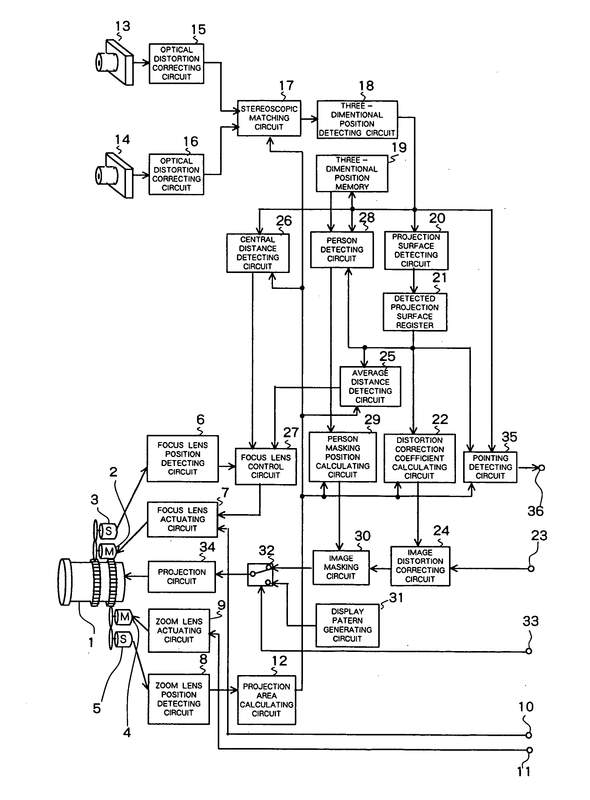
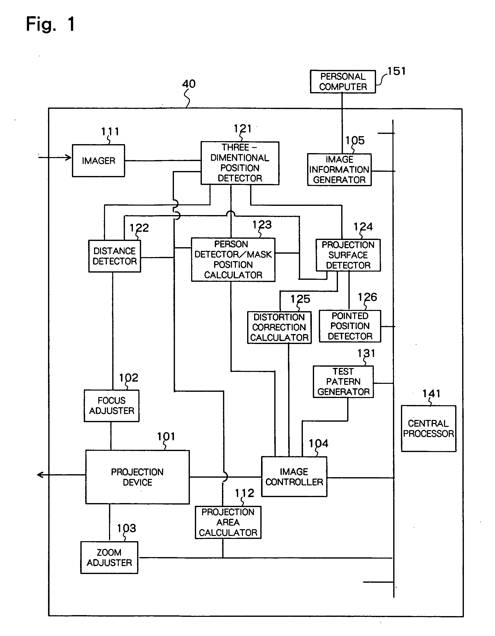
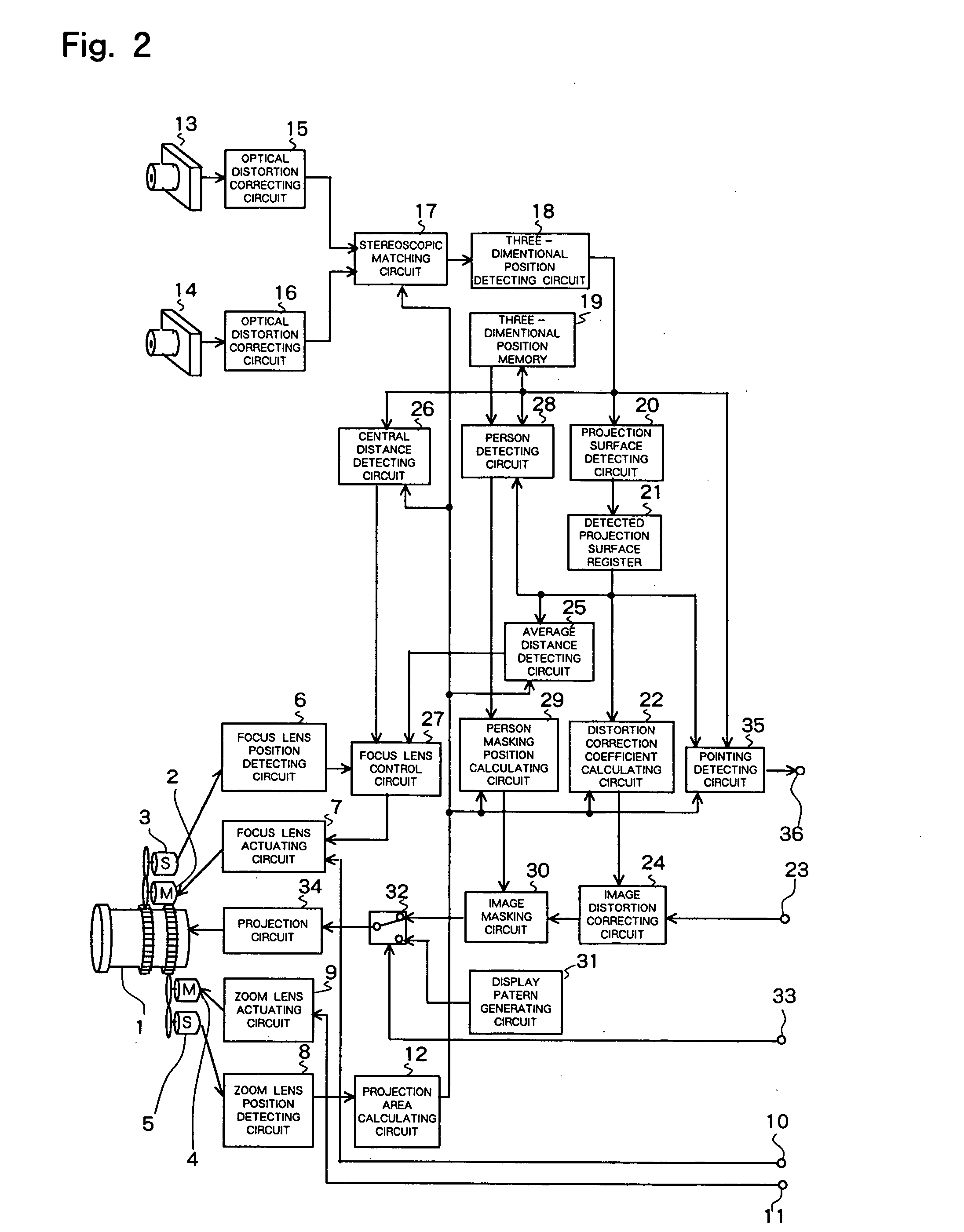
[0055] A projector with a plurality of cameras according to the present invention will be described below with reference to FIGS. 1 and 2.

[0056] As shown in FIG. 1, projector 40 has projection device 101 having a projection lens and a display unit, focus adjuster 102 for adjusting the focus of the projection lens, zoom adjuster 103 for adjusting the zooming of the projection lens, image controller 104 for controlling a projected image, image information generator 105 connected to external personal computer 151 for generating an image, imager 111 having a plurality of cameras, projection area calculator 112 for calculating a projection area from a zoomed position, three-dimensional position detector 121 for detecting the three-dimensional position of a predetermined object point from images captured by the cameras and the projection area, distance detector 122 for detecting the distance up to the object point, person detector / mask position calculator 123 for detecting a person in an ...

second embodiment

[0101] A projector having a plurality of cameras according to the present invention will be described below with reference to FIGS. 18 and 19.

[0102] In the first embodiment, imager 111 has two sets of cameras 13, 14 and distortion correcting circuits 15,16. According to the second embodiment, the imager has three sets of cameras and distortion correcting circuits. Other details of the projector according to the second embodiment are identical to those of the projector according to the first embodiment. Those parts of the projector shown in FIG. 18 which are identical to those shown in FIG. 2 are denoted by identical reference characters, and will not be described in detail below.

[0103] In FIG. 18, camera 37 and distortion correcting circuit 38 are added to cameras 13, 14 and distortion correcting circuits 15, 16 shown in FIG. 2, so that a total of three cameras are employed. The increased number of cameras reduces a dead area, allowing three-dimensional positions to be measured mor...


PUM


Abstract

A projector has a plurality of cameras for adjusting the focus of projected images, correcting projected images that are distorted when images are projected from the projector when it swings from side to side and tilts or when images are projected onto a shaped surface of a projection object, and correcting projected images so that to match the outer profile of the screen if the screen is used as a projection object. The projector has a projection device having a projection lens, a focus adjuster for adjusting the focus of the projection lens, a zoom adjuster for adjusting the zooming of the projection lens, an imager having a plurality of cameras for capturing respective images of a projection object, a projection area calculator for calculating a projection area of an image depending on the distance from the projection lens based on the zoomed position from the zoom adjuster, a three-dimensional position detector for detecting the three-dimensional position of a predetermined object point corresponding to identical object points in the respective images captured by the cameras from the images captured by the cameras and the projection area of the image calculated by the projection area calculator, and a distance detector for detecting the distance up to the object point from the three-dimensional position of the predetermined object point.

Description

BACKGROUND OF THE INVENTION [0001] 1. Field of the Invention [0002] The present invention relates to a projector, and more particularly to a projector having a plurality of cameras for capturing an image projected onto a screen. [0003] 2. Description of the Related Art [0004] In recent years, projectors have been improved to the point where they can be used in a variety of applications. In view of the wide range of applications, it is desirable for the operator to be able to install the projector simply under optimum conditions. To meet such a demand, it is necessary to adjust the focus of projected images to make the projected images sharp and also to correct projected images out of distortion when images are projected from projectors which swings from side to side and tilts or when images are projected onto shaped surfaces of projection objects. [0005] One known rangefinder for use in focus adjustments is an optical shape sensor disclosed in Japanese laid-open patent publication N...

Claims


Application Information

Patent Timeline
IPC IPC(8): G03B35/08G03B21/00G03B21/14H04N5/74H04N13/239H04N13/243
CPCG03B21/14G03B5/02H04N9/3185H04N9/3194G03B21/142G01B11/2513H04N2013/0081H04N13/243H04N13/239
Inventor AOYANAGI, HISAKAZU
Owner NEC DISPLAY SOLUTIONS LTD
Learn More