
Acoustic signal processing method using array coherency

a signal processing and array coherency technology, applied in the field of acoustic borehole tool processing of information, can solve the problems of limited downhole computing power, slow penetration rate, and data acquisition still far exceeding the highest data transmission rate in the mud

Inactive Publication Date: 2005-08-18
HALLIBURTON ENERGY SERVICES INC
View PDF33 Cites 20 Cited by
  • Summary
  • Abstract
  • Description
  • Claims
  • Application Information

AI Technical Summary

Benefits of technology

The patent describes a system and method for characterizing earth formations using a logging tool that passes through a borehole. The method involves repeatedly triggering an acoustic wave generator and recording the acoustic waveforms received by the logging tool. The recorded waveforms are then smoothed using an adaptive wavelet transform or an adaptive moving average filter technique. The smoothing is done by determining the time or frequency semblance of the waveforms and averaging the spacing between peaks. The technical effect of this patent is to provide a more accurate and reliable method for characterizing earth formations using acoustic waves.

Problems solved by technology

While the drilling penetration rate is very slow relative to normal logging rates, data acquisition still can far exceed the highest data transmission rates in the mud.
Thus, in any proposed acoustic LWD art, processing of data downhole may be highly desirable, although the downhole computing power may be limited.
Alternatively, data may be stored in the memory of the downhole tool, but this could require frequent “tripping” of the drill string.
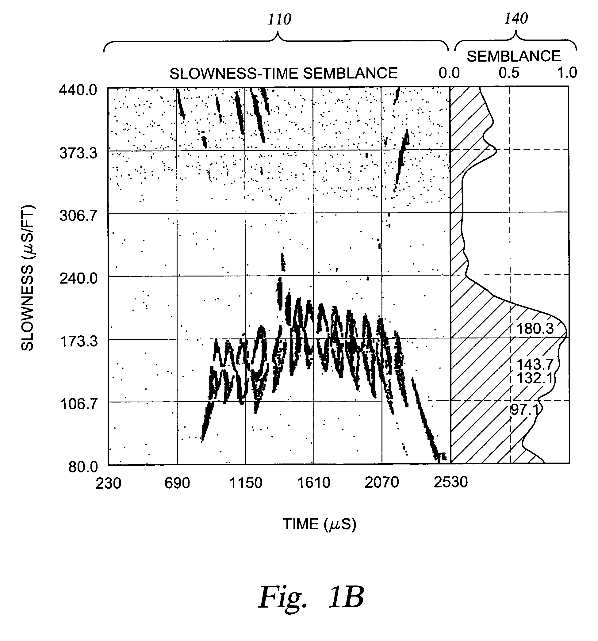
However, windowing the signal may result in inaccuracies and nonlinearities based on the window width for the resulting semblance.
Extrapolating from the windowed semblance often results in adding new errors and amplifying existing errors.

Method used


Image

  • Acoustic signal processing method using array coherency
  • Acoustic signal processing method using array coherency
  • Acoustic signal processing method using array coherency

Examples


Embodiment Construction

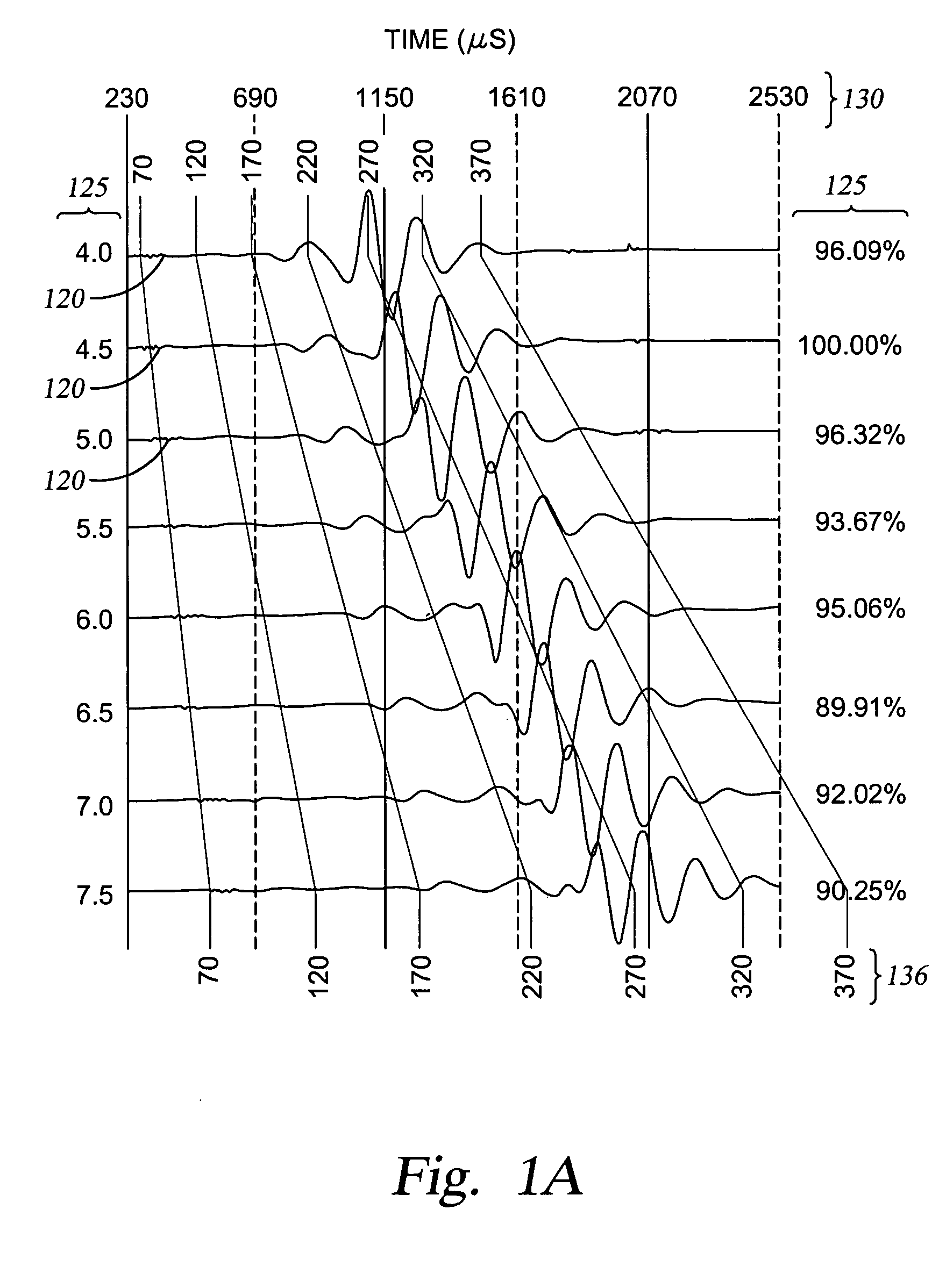
[0023] An acoustic logging tool generally includes several receivers axially spaced along the logging tool. An acoustic transmitter generates an acoustic wave that propagates along the well bore and is detected by the receivers. FIG. 1A shows an example of the data collected by an acoustic logging tool from in response to a the wave generated by the transmitter. Each of the waveforms 120 is recorded by a corresponding receiver as a function of time 130 since the transmitter firing. The receivers are each associated with a distance 125 from the transmitter. After recording the waveforms, the logging tool typically normalizes the waveform so that they have the same signal energy, and FIG. 1A expresses the normalization factor as a percentage of transmitted signal energy 135.

[0024]FIG. 1A also shows a graduated series of sloping lines to indicate the relative waveform delays to be expected for given slowness values 136. Slower waves (those having larger slowness values) take longer to...


PUM


Abstract

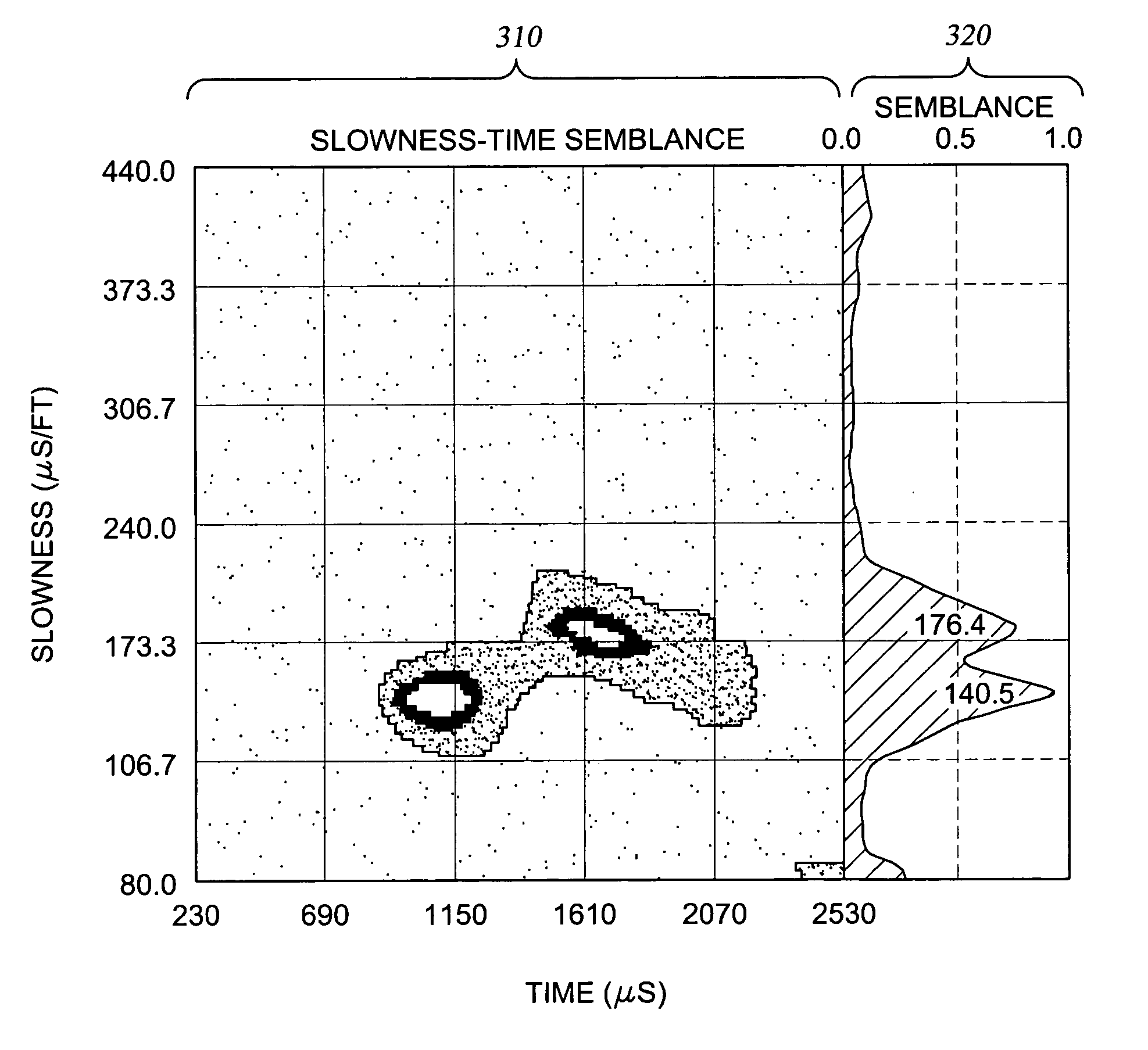
A system and method is provided for characterizing earth formations. In one embodiment, the method includes passing a logging tool through a borehole and repeatedly: (a) triggering an acoustic wave generator; (b) recording acoustic waveforms received by receivers in the logging tool; (c) determining a time semblance of the recorded acoustic waveforms; and (d) smoothing the time semblance. In a different embodiment, a phase semblance of the recorded acoustic waveforms is determined and smoothed. The smoothing may be performed using an adaptive wavelet denoising technique or an adaptive moving average filter technique. In each case the average time or frequency spacing between semblance peaks is preferably determined and used to adapt the smoothing operation in a manner that varies with the slowness value s.

Description

CROSS-REFERENCE TO RELATED APPLICATIONS [0001] This application is a divisional application of U.S. patent application Ser. No. 10 / 827,776, titled, Acoustic Signal Processing Method Using Array Coherency, filed on Apr. 20, 2004, whose inventor is Batakrishna Mandal, which is a divisional of U.S. patent application Ser. No. 09 / 860,294, titled, Acoustic Signal Processing Method Using Array Coherency, filed on May 18, 2001, whose inventor is Batakrishna Mandal, which claims priority to U.S. Provisional Patent Application Application Ser. No. 60 / 254,316, filed Dec. 8, 2000, entitled “Array Coherency Method Of Signals,” whose inventor is Batakrishna Mandal, all hereby incorporated herein by reference in their entirety.BACKGROUND OF THE INVENTION [0002] 1. Field of the Invention [0003] The present invention relates broadly to the processing of information obtained by an acoustic borehole tool. More particularly, the invention relates to the real-time or post-processing of acoustic wave da...

Claims


Application Information

Patent Timeline
Patent Type & Authority Applications(United States)
IPC IPC(8): G01V1/48
CPCG01V1/48
Inventor MANDAL, BATAKRISHNA
Owner HALLIBURTON ENERGY SERVICES INC
Learn More