Fan array fan section in air-handling systems

a technology of fan array and air-handling system, which is applied in the field offan array fan section, can solve the problems of high operating cost of single fan unit b>100/b>, extremely large space (e.g. structure space), and inconvenient operation of large air-handling compartments

Active Publication Date: 2005-08-18
NORTEK AIR SOLUTIONS +1
View PDF56 Cites 39 Cited by
  • Summary
  • Abstract
  • Description
  • Claims
  • Application Information

AI Technical Summary

Problems solved by technology

These prior art air-handling systems have many problems including the following exemplary problems: Because real estate (e.g. structure space) is extremely expensive, the larger size of the air-handling compartment 102 is extremely undesirable.
The single fan units 100 are expensive to produce and are generally custom produced for each job.
Single fan units 100 are expensive to operate.
Single fan units 100 are inefficient in that they only have optimal or peak efficiency over a small portion of their operating range.
The high mass and turbulence of the large fan unit 100 can cause undesirable vibration.
The two fan unit 100 air-handling systems, however, still substantially suffered from the problems of the single unit embodiments.
The Bonet system would not work to direct air flow to all devices in the direction of general air flow.
Even in the computer and machine industries, however, operating fans in parallel is taught against as not providing the desired results except in low system resistance situations where fans operate in near free delivery.

Method used


Image

  • Fan array fan section in air-handling systems
  • Fan array fan section in air-handling systems
  • Fan array fan section in air-handling systems

Examples


Embodiment Construction

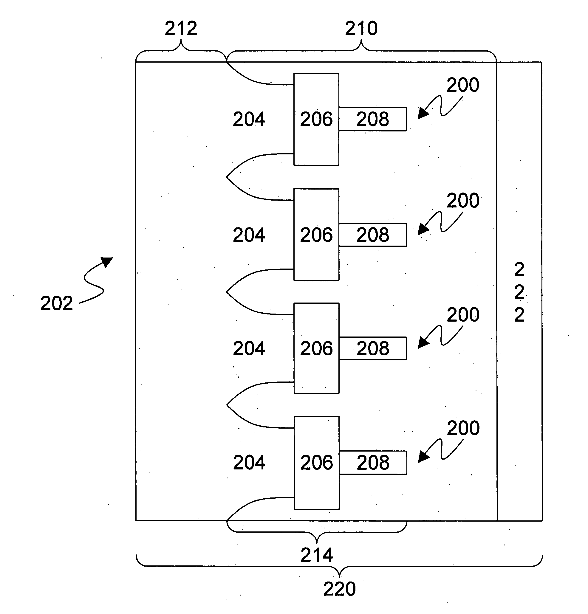
[0043] The present invention is directed to a fan array fan section in an air-handling system. As shown in FIGS. 3-12, the fan array fan section in the air-handling system uses a plurality of individual single fan units 200. In one preferred embodiment, the fan units 200 are arranged in a true array (FIGS. 4-8), but alternative embodiments may include, for example, alternative arrangements such as in a spaced pattern (FIG. 9), a checker board (FIG. 10), rows slightly offset (FIG. 11), or columns slightly offset (FIG. 12). As the present invention could be implemented with true arrays and / or alternative arrays, the term “array” is meant to be comprehensive.

[0044] The fan units 200 in the fan array of the present invention may be spaced as little as 20% of a fan wheel diameter. Optimum operating conditions for a closely arranged array may be found at distances as low as 30% to 60% of a fan wheel diameter. By closely spacing the fan units 200, more air may be moved in a smaller space....


PUM

PropertyMeasurementUnit
diameteraaaaaaaaaa
diameteraaaaaaaaaa
diameteraaaaaaaaaa

Abstract

A fan array fan section in an air-handling system includes a plurality of fan units arranged in a fan array. Each fan unit is positioned within a fan unit chamber / cell. Each fan unit chamber / cell has at least one acoustically absorptive insulation surface. The insulation surfaces of the fan unit chambers / cells together form a coplanar silencer. Sound waves from the fan units passing through the insulation surface at least partially dissipate as they pass therethrough. In one preferred embodiments the fan unit chamber / cell is a cell having a frame that supports the insulation surfaces.

Description

[0001] The present application is a continuation-in-part application of patent application Ser. No. 10 / 806,775, filed Mar. 22, 2004, and entitled FAN ARRAY FAN SECTION IN AIR-HANDLING SYSTEMS. patent application Ser. No. 10 / 806,775 is a nonprovisional application claiming the benefit under 35 USC Section 119(e) of U.S. Provisional Patent Application Ser. No. 60 / 554,702, filed Mar. 20, 2004, and entitled FAN ARRAY FAN SECTION IN AIR-HANDLING SYSTEMS. Patent application Ser. No. 10 / 806,775 is a nonprovisional application claiming the benefit under 35 USC Section 119(e) of U.S. Provisional Patent Application Ser. No. 60 / 456,413, filed Mar. 20, 2003, and entitled FAN ARRAY FAN SECTION IN AIR-HANDLING SYSTEMS. The present application is a continuation-in-part application of PCT Patent Application Serial Number PCT / U.S. 2004 / 008578, filed Mar. 19, 2004, and entitled FAN ARRAY FAN SECTION IN AIR-HANDLING SYSTEMS. The present application is based on and claims priority from these applicatio...

Claims


Application Information

Patent Timeline
Patent Type & Authority Applications(United States)
IPC IPC(8): F04D25/16F24F7/06
CPCF04D25/166F24F3/044F24F7/06F24F7/065F24F11/0079F24F13/24Y10T29/49826Y02B30/746F04D15/00Y02B30/767F04D29/664Y10T29/49245F24F2013/242F24F11/77Y02B30/70F24F1/0033F04D13/06F05D2260/96F04D13/12F05D2250/511F04D15/0066
Inventor HOPKINS, LAWRENCE G.
Owner NORTEK AIR SOLUTIONS
Why Eureka
Try Eureka