Methods and systems for signal amplification through envelope removal and restoration

Inactive Publication Date: 2005-08-18
ZARBANA DIGITAL FUND
View PDF4 Cites 75 Cited by
  • Summary
  • Abstract
  • Description
  • Claims
  • Application Information

AI Technical Summary

Benefits of technology

[0008] Thus a need exists for an amplification system, capable of amplifying, among other things, wireless communication signals with greater efficiency and accuracy than that found in the prior art. In satisfaction of these needs, embodiments of the present invention comprise systems, methods, and devices for amplifying electromagnetic signals by decomposing each signal into a plurality of near-constant envelope signals, removing residual amplitude modulation from these signals, thereby creating a constant envelope signal; amplifying each signal independently, and recombining the amplified constant envelope signals. In the preferred embodiment a plurality of control signals, each corresponding to the magnitude of a respective near-constant envelope signal, is employed to amplify each near-constant envelope signal in inverse proportion to its corresponding control signal. This inverse amplification preferably eliminates any unwanted residual amplitude modulation thus producing an amplified constant envelope signal. The plurality of amplified constant envelope signals is then preferably combined to form an amplified version of the incoming original signal.
[0009] In accordance with one aspect of the invention, a method is provided for amplifying a signal. This method includes decomposing a signal into a plurality of near-constant envelope signals, producing a plurality of control signals, where each control signal corresponds to the magnitude of a respective near-constant envelope signal, and then amplifying each near-constant envelope signal in inverse proportion to its corresponding control signal. In various embodiments of this method, the plurality of inversely amplified near-constant envelope signals is then combined to produce an amplified output signal. In some embodiments, decomposing the signals is performed via LINC signal decomposition. Embodiments of this method may also include using an adjustable gain amplifier to amplify each near-constant signal. Additionally, some embodiments of this method use a Chireix style amplitude combiner to combine the signals, while other embodiments use a conventional power combiner.
[0010] I

Problems solved by technology

In most RF transmitters, the PA handles the largest power within the transmitter and inefficiency in the PA typically accounts for much of the wasted power in the transmitter.
Unfortunately, in many applications, the PA does not perform the task of power amplification efficiently, consuming much more power than is actually transmitted.
This excess power generation can be costly, especially in battery operated devices, because it often necessitates the use of larger-capacity batteries, and / or shorter battery recharging intervals.
Unfortunately, as the PA is driven into compression, the signal spectrum tends to widen, due to nonlinear distortions.
This spectral widening is called spectral regrowth, and is undesirable because it spills RF energy into adjacent frequency channels.
The energy spilled into other channels is known as Adjacent Channel Power (ACP) emissions and is often undesirable because it may cause interference with communication systems operating in the other channels.
Thus, tradeoffs exist between efficiency and ACP emissions, even for constant-envelope PAs.
Non-constant envelope signals, such as Differential Quadrature Phase Shift Keying (DQPSK) and spread spectrum signals, make the PA efficiency problem even more difficult because the modulation may cause the amplitude of the envelope to vary by 14 dB or more.
Peak-to-average power is important because clipping occurs when the peak-power capabilities of the PA are exceeded, and clipping introduces much distortion.
To become even more efficient, some systems push the peak power output into saturation, but this can result in unacceptable ACP emissions.
This push into saturation can also cause distortions in the in-band modulation accuracy, which is called Error-Vector Modulation (EVM) accuracy, and is specified in terms of RMS error from an ideally modulated signal.
Unfortunately, most saturation regions are narrow (often less than the 3 dB peak-to-average criterion given above for π / 4 DQPSK), and thus only allow modest pre-distortion (and efficiency) improvements.
Prior art PA designs are particularly inefficient when operating at less than full output power, as is common in systems that use adaptive power control.
However, many of the desired gains promised by adaptive power control have not been realized because the power saved by transmitting at reduced power is lost because the overall PA is less efficient at reduced power.
However, a key problem in LINC amplification is that the band limiting and quantization effects in the decomposition process produces component signals having residual amplitude modulation.
Thus the component signals are not constant envelope signals, but rather near-constant envelope signals, and as a result the amplification is inaccurate.

Method used


Image

  • Methods and systems for signal amplification through envelope removal and restoration
  • Methods and systems for signal amplification through envelope removal and restoration
  • Methods and systems for signal amplification through envelope removal and restoration

Examples


Embodiment Construction

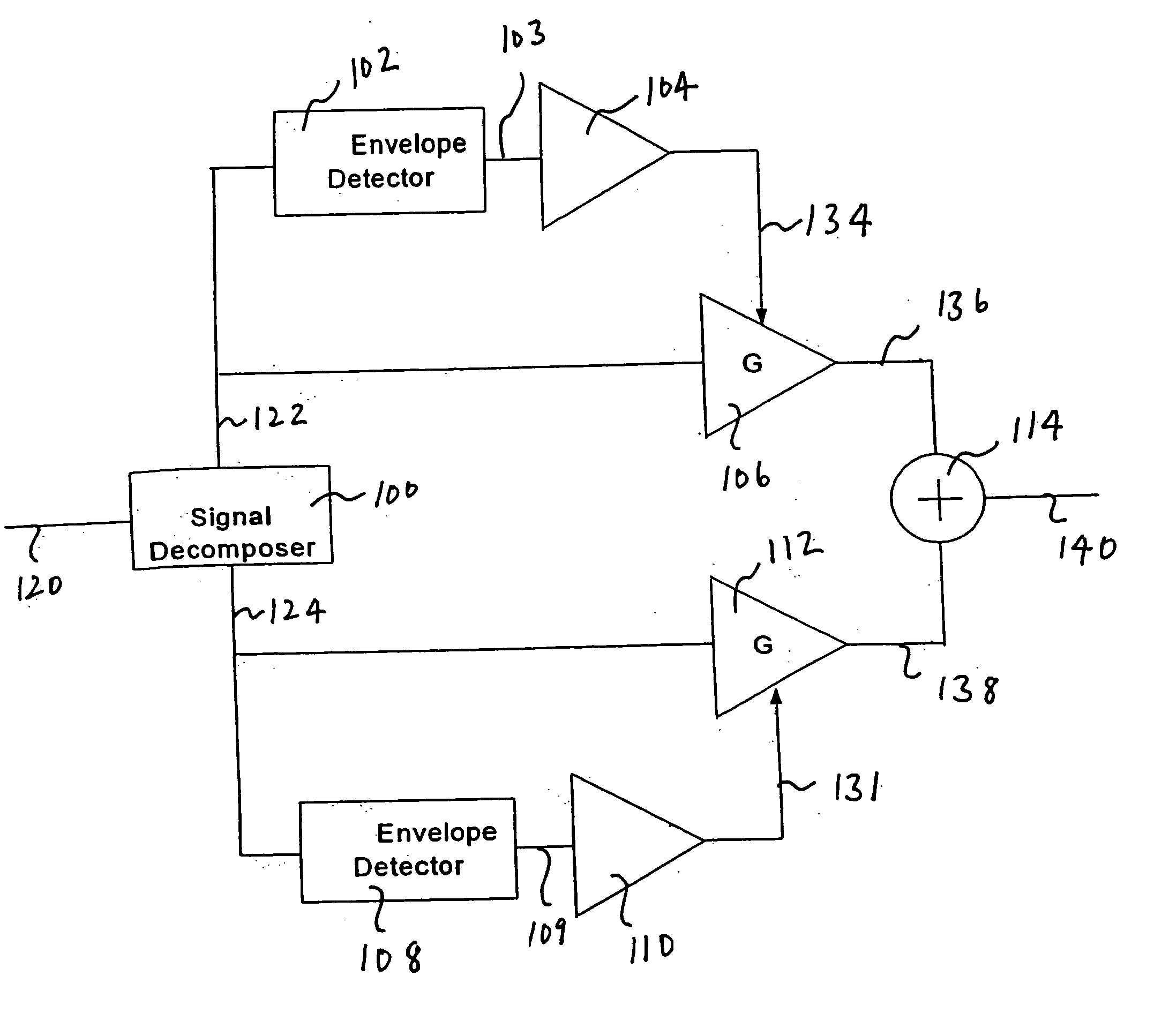
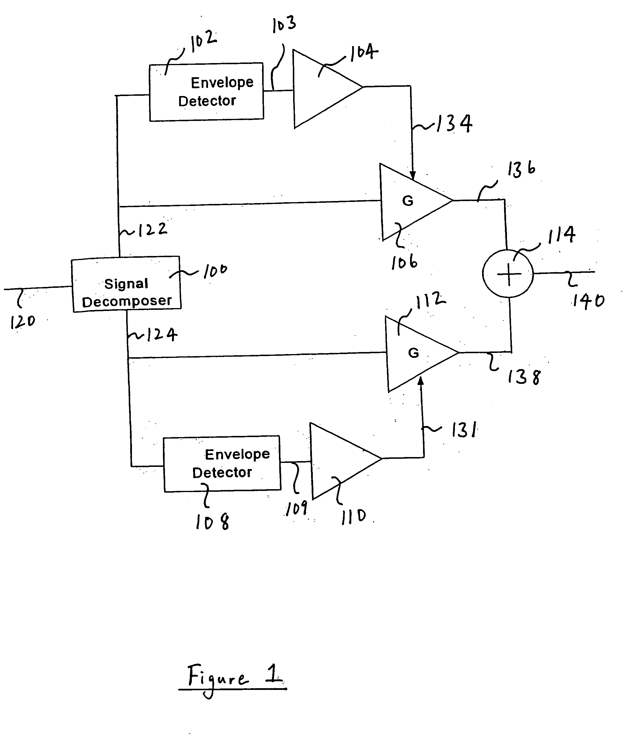
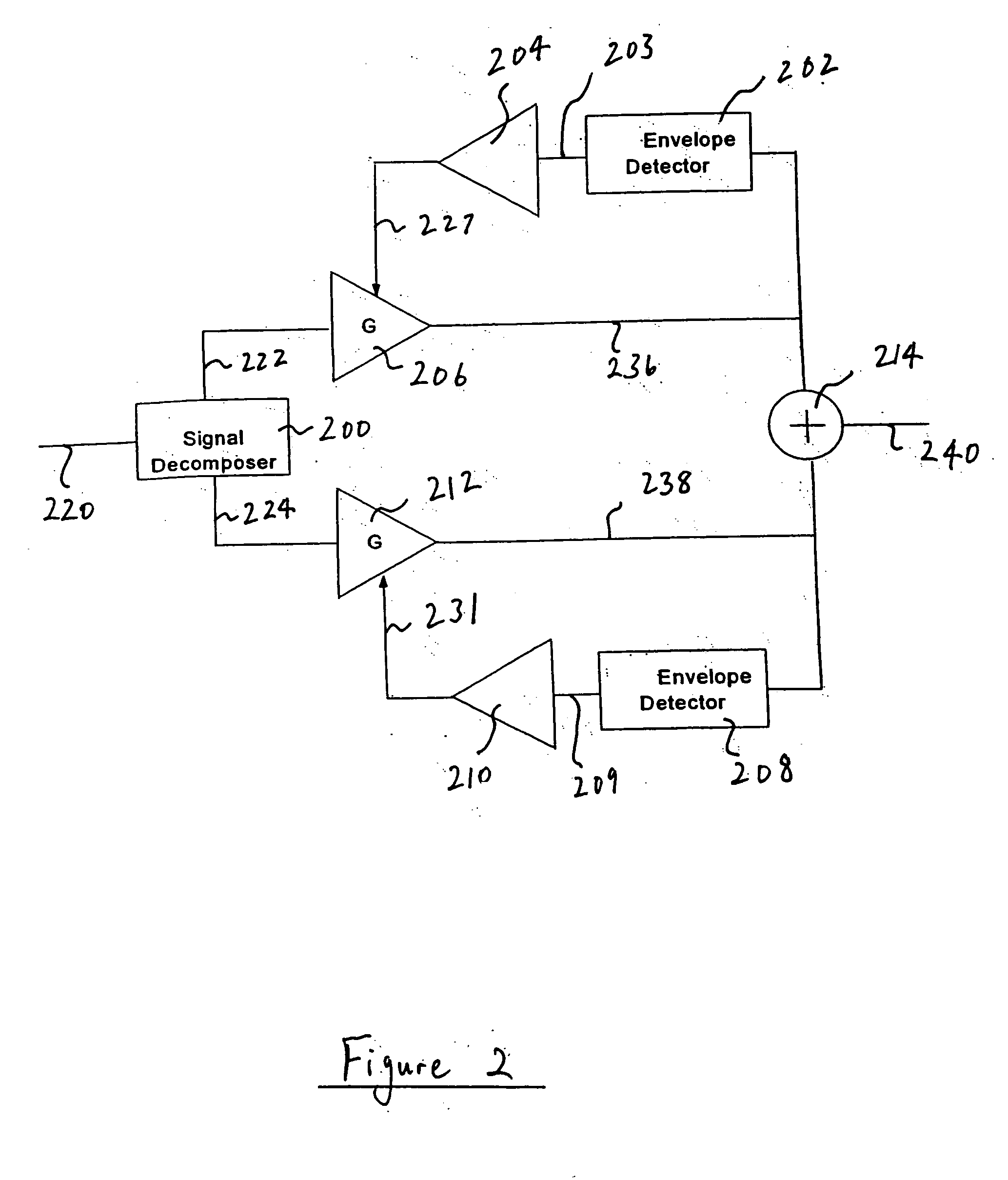
[0017] In brief overview embodiments of the present invention amplify an incoming signal by first decomposing the signal into a plurality of near-constant envelope signals. Ideally, this decomposition should produce a plurality of constant envelope signals, but due to band limiting and quantization effects in the decomposition process, the output signals retain a residual amplitude modulation and are hence described as near-constant envelope signals. Embodiments of the present invention also produce a plurality of control signals, each corresponding to the magnitude of a respective near-constant envelope signal. The plurality of control signals are used to amplify each near-constant envelope signal in inverse proportion to its corresponding control signal. This inverse amplification eliminates the unwanted residual amplitude modulation thus producing an amplified constant envelope signal. The plurality of amplified constant envelope signals can then be combined to form an amplified ...


PUM


Abstract

Embodiments of the present invention comprise systems, methods, and devices for amplifying electromagnetic signals by decomposing each signal into a plurality of near-constant envelope signals, removing residual amplitude modulation from these signals, amplifying each signal independently, and recombining the amplified signals. In the preferred embodiment a plurality of control signals, each corresponding to the magnitude of a respective near-constant envelope signal, is employed to amplify each near-constant envelope signal in inverse proportion to its corresponding control signal. This inverse amplification preferably eliminates any unwanted residual amplitude modulation thus producing an amplified constant envelope signal. The plurality of amplified constant envelope signals is then preferably combined to form an amplified version of the incoming signal.

Description

FIELD OF THE INVENTION [0001] The present invention relates generally to amplification of signals, and more specifically to amplification and subsequent recombination of a decomposed signal. BACKGROUND OF THE INVENTION [0002] Radio Frequency (RF) transmitters typically use an RF Power Amplifier (PA) to provide the RF signal strength needed for radio communications over a distance. The output of the PA is typically provided to a transmitting antenna, and thus the power output of the PA is proportional to the transmitted power. As the output power of the PA increases, the power radiated by the transmitting antenna increases and the useable range of the transmitter increases. [0003] In most RF transmitters, the PA handles the largest power within the transmitter and inefficiency in the PA typically accounts for much of the wasted power in the transmitter. Unfortunately, in many applications, the PA does not perform the task of power amplification efficiently, consuming much more power ...

Claims


Application Information

Patent Timeline
IPC IPC(8): H03F3/00H03F3/189H03G3/00H03G3/30H04B1/02
CPCH03G3/3042H03F1/0294H03F3/00H03F3/189H03G3/00H04B1/02
Inventor WIGHT, JAMES STUART
Owner ZARBANA DIGITAL FUND
Why Eureka
Try Eureka