Emboli filtration system and methods of use

a filtration system and filtration system technology, applied in the field of emboli filtration system and methods of use, can solve the problems of ischemic injury, plaque pieces (“emboli”) often being dislodged from the stenosis or the vessel wall, damage to the organ or limb, etc., and achieve the effect of preventing bypass flow around the filter

Inactive Publication Date: 2005-08-18
BOSTON SCI SCIMED INC
View PDF99 Cites 42 Cited by
  • Summary
  • Abstract
  • Description
  • Claims
  • Application Information

AI Technical Summary

Benefits of technology

[0018] It is also an object of this invention to provide emboli filtration apparatus and methods that reduce the risk of emboli escaping from a filter element.
[0019] It is a further object of the present invention to provide emboli filtration apparatus and methods that reduce the risk of trauma to vessel endothelium resulting from movement transferred to the emboli filtration apparatus.
[0020] It is still a further object of the present invention to provide emboli filtration apparatus and methods that enable a filter element to be repositioned during a medical procedure without having to remove or insert additional interventional devices.
[0021] These and other objects of the present invention are accomplished by providing emboli filtration apparatus comprising a guide wire having a filter element captured thereon, so that the guide wire is free to rotate and translate while the filter element remains stationary. The apparatus thus allows for movement and rotation of the guide wire as devices are advanced over it to treat a stenosis, substantially without dislodging the filter element. Accordingly, the risk of permitting emboli to escape during temporary displacement or skewing of the filter element is reduced, as well as movement-induced trauma of the vessel endothelium.
[0023] The filter element includes a proximal capture ring having a diameter that is larger than the diameter of the guide wire, but smaller than the diameter of the distal tip of the guide wire. The capture ring allows the guide wire to move freely relative to the filter element over a limited range, so that movement or rotation of the guide wire does not cause the filter to move or to scrape against the walls of the vessel. When it is desired to retract the filter element, the guide wire is pulled proximally so that the distal tip of the guide wire engages the capture ring and pulls the filter element back into a sheath to its contracted state.
[0024] Optionally, the filter element may include a cylindrical sleeve that ensures that the filter forms an adequate seal against the walls of the vessel in the deployed state, thus preventing bypass flow around the filter. The sleeve also assists in orienting the axis of the filter element parallel to the axis of the vessel.

Problems solved by technology

In such diseases, the flow areas of blood vessels become narrowed or occluded by the buildup of plaque on the walls of the vessels, leading to ischemia, and depending upon the location of the vessel, damage to the organ or limb.
One problem frequently encountered during such procedures is that pieces of plaque (“emboli”) often are dislodged from the stenosis or the vessel wall.
Such emboli may travel into smaller diameter regions of the vasculature, blocking blood vessels and causing ischemic injury.
This problem is especially severe where the emboli are permitted to travel into the coronary arteries and carotid arteries, and can result in infarction, stroke and even death.
A key disadvantage of previously known emboli filtration systems, such as described in the foregoing patents, is that the filters in those devices are fixedly attached to the guide wire or angioplasty catheter, respectively.
If the catheter or guide wire is rotated, bumped or moved after the filter has been deployed, there is a substantial risk that the filter will become temporarily dislodged or skewed, thereby permitting emboli to escape past the filter.
One drawback associated with the device described in the Gilson patent is that the guide wire is delivered into the patient's vessel with the filter element disposed in a collapsed state between the proximal and distal stops near the distal end of the guide wire.
The placement of the filter element near the distal end of the guide wire during delivery may make it difficult for the guide wire to negotiate tortuous anatomy during delivery.

Method used


Image

  • Emboli filtration system and methods of use
  • Emboli filtration system and methods of use
  • Emboli filtration system and methods of use

Examples


Embodiment Construction

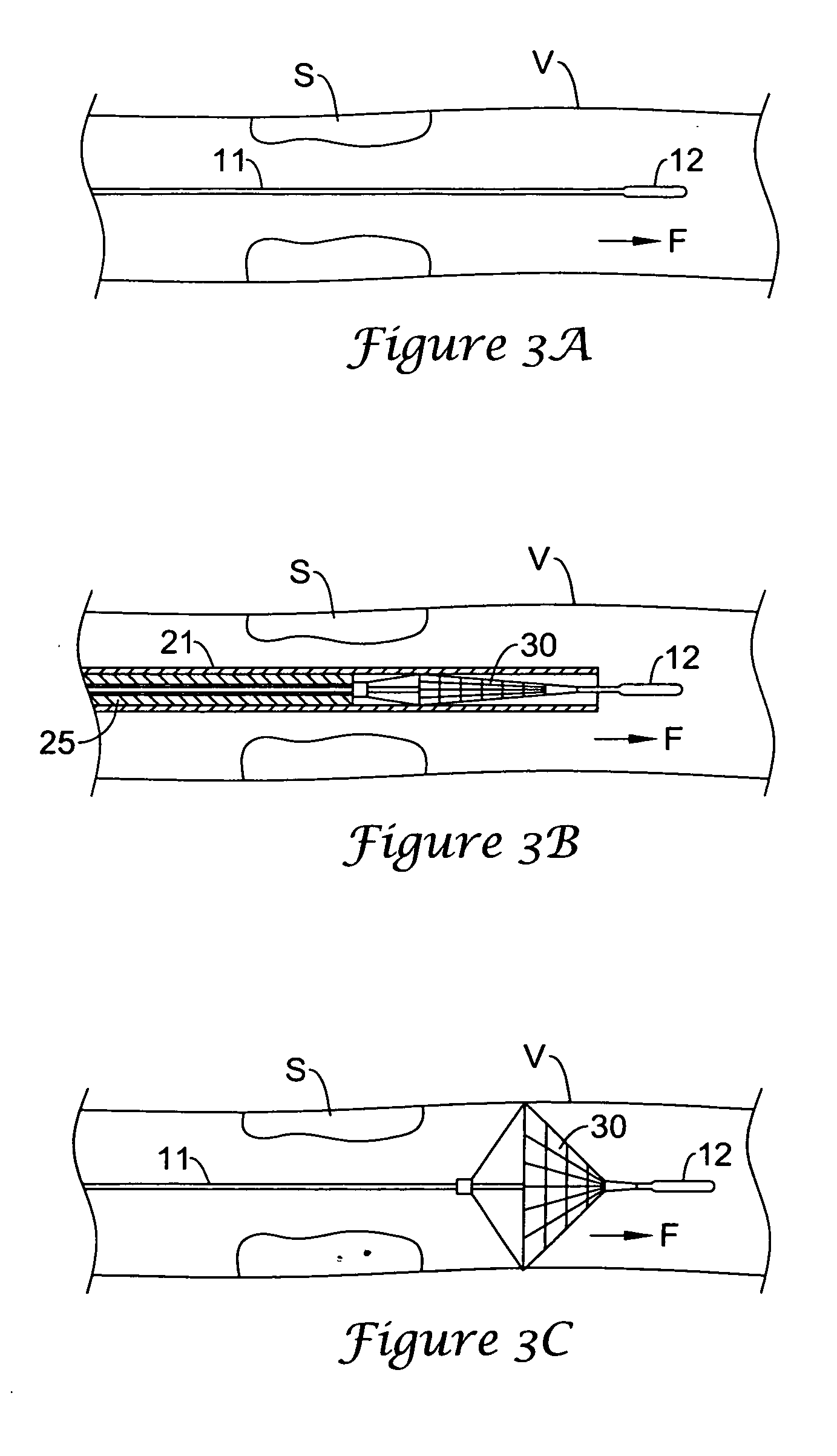
[0036] The present invention is directed to an emboli filtration system and methods that filter out emboli generated during surgical or percutaneous interventional procedures. In accordance with the principles of the present invention, a filter element is captured on a guide wire so that the guide wire is capable of rotation and translation, without disturbing the placement of the filter element. Because the filter element is captured on the guide wire, however, the filter element is readily removed by retracting the guide wire into a sheath.

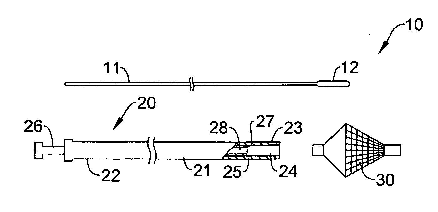
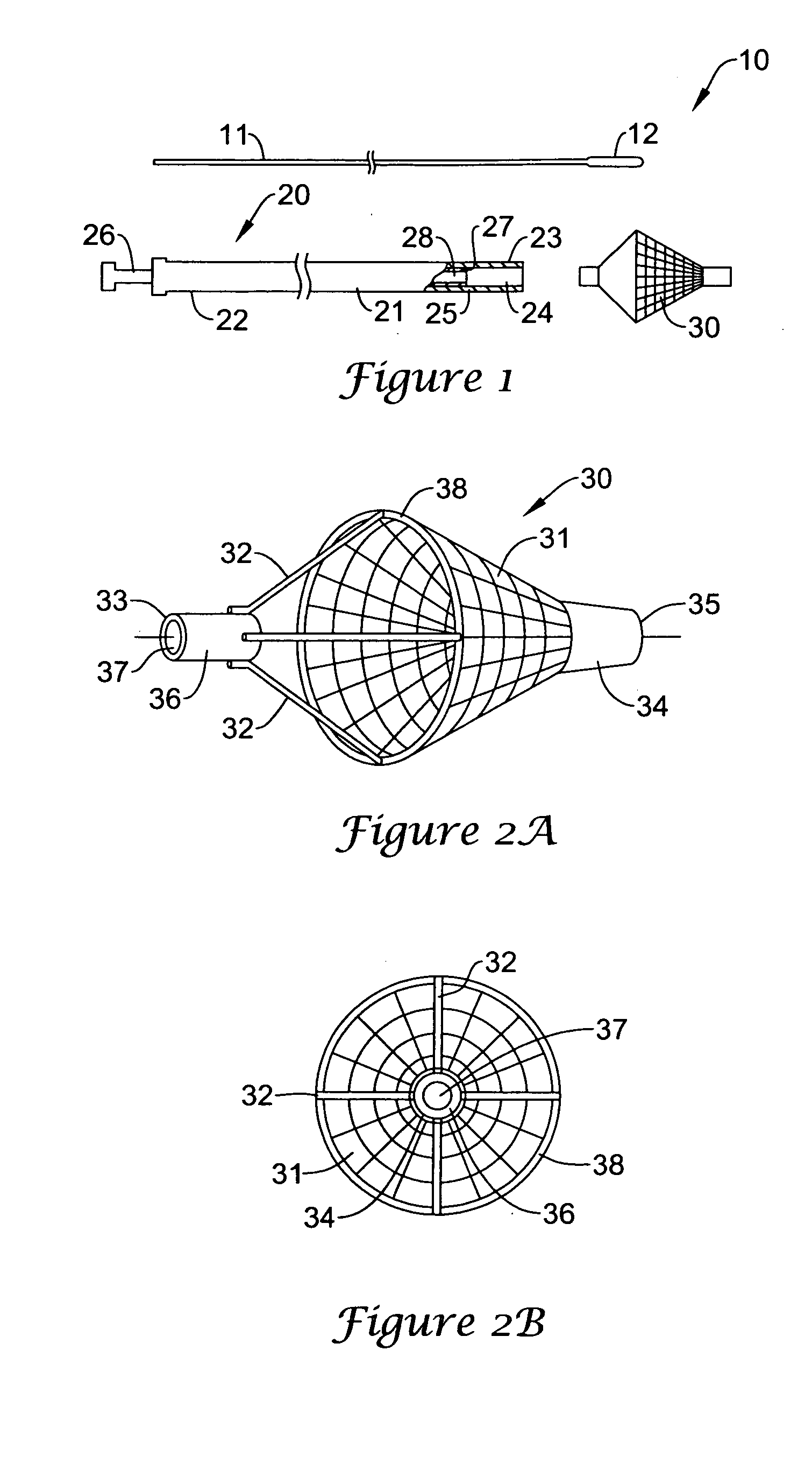
[0037] Referring to FIG. 1, apparatus 10 of a first embodiment of the present invention comprises guide wire 11, delivery sheath 20 and filter element 30. In accordance with the principles of the present invention, guide wire 11 includes enlarged diameter distal region 12. Guide wire 11 may be constructed of material commonly used in guide wire construction, such as stainless steel or a high strength polymer. Distal region 12, which acts as a d...


PUM


Abstract

An emboli filtration apparatus is provided comprising a guide wire having a filter element captured thereon, so that the guide wire is free to rotate and translate while the filter element remains stationary. The apparatus allows for movement and rotation of the guide wire as devices are advanced over it to treat occlusive disease, substantially without dislodging the filter element. In a preferred embodiment, the guide wire comprises a proximal stop configured to reposition the filter element during a medical procedure without having to remove or insert additional interventional devices.

Description

REFERENCE TO RELATED APPLICATIONS [0001] The present application is a continuation-in-part of U.S. patent application Ser. No. 09 / 774,197, filed Jan. 29, 2001, which is a continuation-in-part of U.S. patent application Ser. No. 09 / 354,897, filed Jul. 16, 1999, now U.S. Pat. No. 6,179,859.FIELD OF THE INVENTION [0002] The present invention relates to apparatus and methods for removing emboli from the blood stream that are generated during treatment of vascular disease, such as angioplasty, atherectomy or stenting. More particularly, an emboli filtration device and methods are provided having a captured filter that enables movement of a guide wire associated with the filter without displacing the filter. BACKGROUND OF THE INVENTION [0003] Atherosclerosis and other vascular occlusive diseases are becoming prevalent today in many developed countries. In such diseases, the flow areas of blood vessels become narrowed or occluded by the buildup of plaque on the walls of the vessels, leadin...

Claims


Application Information

Patent Timeline
Patent Type & Authority Applications(United States)
IPC IPC(8): A61F2/01A61M29/02
CPCA61F2/01A61F2/013A61F2002/011A61F2002/015A61F2230/0067A61M2025/09183A61F2002/018A61F2230/0006A61M25/104A61F2/0108A61F2/011
Inventor BATES, MARK C.HOGENDIJK, MICHAELPISANO, NICOLA A.
Owner BOSTON SCI SCIMED INC
Why Eureka
Try Eureka