Concealed elevated post base bracket

a technology of elevated posts and brackets, applied in the direction of buildings, buildings, towers, etc., can solve the problems of prior art requiring a non-aesthetically pleasing and potentially unsafe raised concrete curb or platform

Inactive Publication Date: 2005-08-25
MCCARTHY BRIAN PATRICK
View PDF4 Cites 9 Cited by
  • Summary
  • Abstract
  • Description
  • Claims
  • Application Information

AI Technical Summary

Benefits of technology

[0005] This invention achieves this requirement and also provides for an aesthetically pleasing and potentially safer solution by eli...

Problems solved by technology

To meet this requirement, prior art requires a non-aesthetically pleasing and potentia...

Method used


Image

  • Concealed elevated post base bracket
  • Concealed elevated post base bracket

Examples


Embodiment Construction

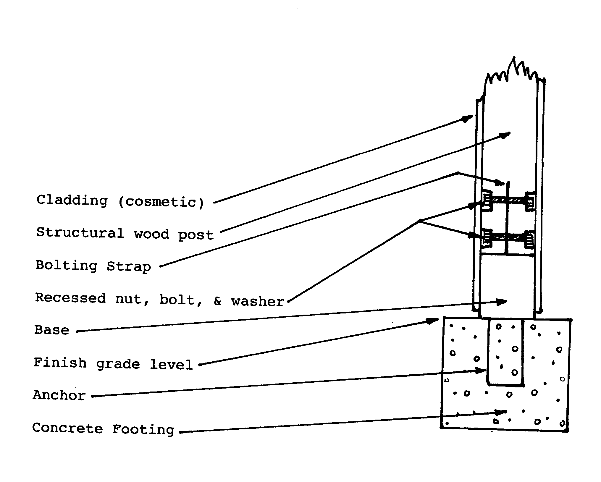
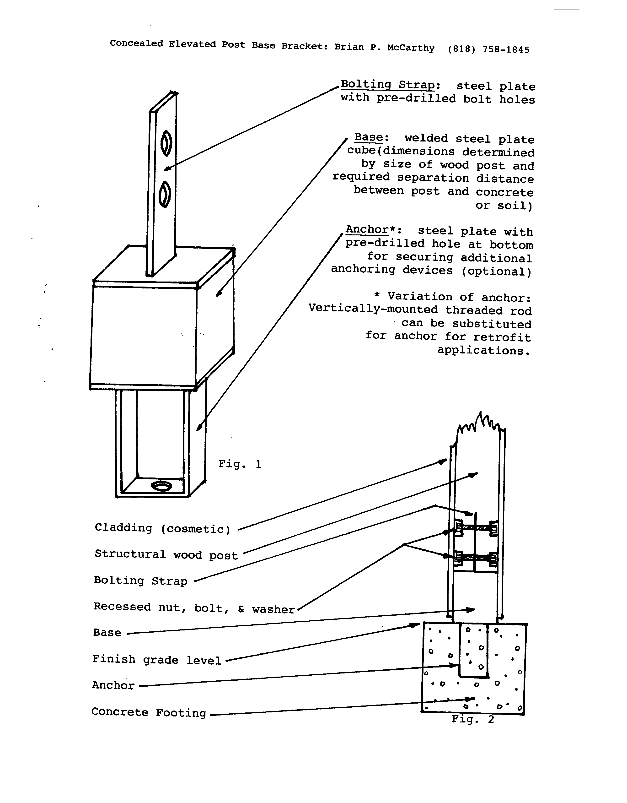
[0008] The invention consists of three basic parts: anchor, base, and bolting strap. When welded together, they form the bracket. The bracket can be made to accommodate the various standard sizes of wood posts (nominally known as 4×4, 6×6, 8×8, etc.) The anchor portion of the bracket is set in a fresh concrete footing or foundation prior to pouring concrete.

[0009] The base rests above grade with the bolting strap welded atop it. Threaded rods, anchor bolts, or other devices can be mounted to the bottom of the anchor if additional embedment is required.

[0010] For retrofit applications, a variation of the bracket can have a threaded rod mounted vertically to the bottom of the base in lieu of the standard anchor. The bracket can then be epoxy-set into a suitable existing footing or foundation.

[0011] The bracket can be manufactured using readily available raw steel and standard welding techniques.


PUM


Abstract

Pending structural engineer approval, the invention replaces previous technology for creating vertical separation between concrete or soil and exposed structural wood posts. Previous accommodations for this requirement call for obtrusive raised concrete bases (considerably wider than the posts themselves) under the posts. Such bases create the potential for personal injury and are visually unappealing. The bracket base is of equal size and shape to the bottom of the cross-cut wood post. The single center-mounted bolting strap allows for recessing the nuts, bolts, and washers flush to the outside of the post. There are, thus, continuous planes along the four sides of the post from its top to the bottom of the exposed bracket. The entire post and bracket can be clad with any suitable material (wood, manufactured sidings, aluminum, vinyl, etc.) to conceal the entire bracket and structural post.

Description

CROSS REFERENCE TO RELATED APPLICATIONS [0001] Not Applicable STATEMENT REGARDING FEDERALLY SPONSORED RESEARCH OR DEVELOPMENT [0002] Not Applicable REFERENCE TO A SEQUENCE LISTING, A TABLE, OR A COMPUTER PROGRAM LISTING COMPACT DISC APPENDIX [0003] Not Applicable BACKGROUND OF THE INVENTION [0004] This invention pertains to the field of building construction. Structural engineers and local building codes may require a minimum of 6″ vertical separation distance between concrete or soil (at grade) and exposed structural wood posts to prevent rotting of the wood post. To meet this requirement, prior art requires a non-aesthetically pleasing and potentially unsafe raised concrete curb or platform at the base of a steel bracket-mounted wood post. BRIEF SUMMARY OF THE INVENTION [0005] This invention achieves this requirement and also provides for an aesthetically pleasing and potentially safer solution by eliminating the concrete platform and completely concealing the otherwise unappealin...

Claims


Application Information

Patent Timeline
IPC IPC(8): E02D27/00E02D27/32E04H12/22
CPCE04H12/2253
Inventor MCCARTHY, BRIAN PATRICK
Owner MCCARTHY BRIAN PATRICK
Why Eureka
Try Eureka