Single core stereo optical device having spherical gradient refractive exponent spherical lens

A technology of optical equipment and spherical gradient, applied in the direction of optics, stereo system, optical components, etc., can solve the problem of spherical aberration limited by the size of the exit pupil, and achieve the effect of low cost and high light efficiency

Inactive Publication Date: 2004-10-27
EASTMAN KODAK CO
View PDF13 Cites 4 Cited by
  • Summary
  • Abstract
  • Description
  • Claims
  • Application Information

AI Technical Summary

Problems solved by technology

The setup of Kessler et al. provides a solution using a ball lens that reduces aberrations in image distortion, but there is still room for improvement
For example, conventional ball lenses have limitations on the size of the exit pupil and contain uncorrected spherical aberration

Method used


Image

  • Single core stereo optical device having spherical gradient refractive exponent spherical lens
  • Single core stereo optical device having spherical gradient refractive exponent spherical lens
  • Single core stereo optical device having spherical gradient refractive exponent spherical lens

Examples


Embodiment Construction

[0063] The description is particularly directed to elements forming part of, or more directly co-operating with, the apparatus of the invention. It will be apparent that elements not particularly shown or described may take various forms well known to those skilled in the art.

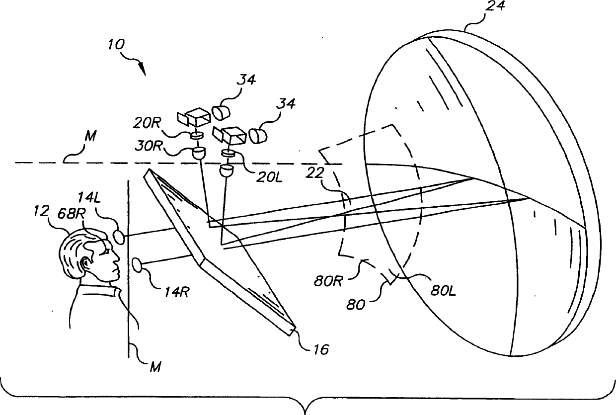
[0064] Referring to FIG. 1 , a perspective view of an autostereoscopic imaging system 10 is shown. Viewer 12 is generally seated and views virtual stereoscopic images from left and right viewing pupils 141 and 14r. Optimal viewing conditions are obtained when the left and right pupils 681 (not shown in FIG. 1 ) and 68r of the viewer 12 coincide with the positions of the left and right viewing pupils 141 and 14r.

[0065] The right optical system 20r directs the image to the beam splitter 16 through the right ball lens assembly 30r. A right curved image 80 r is formed on the front focal plane 22 of the curved mirror 24 so as to be located between the right ball lens 30 r and the curved mirror 24 .

...


PUM


Abstract

A monocentric autostereoscopic optical apparatus (10) for viewing a virtual image, electronically generated and projected on a curved surface. For each left and right image component, a separate optical system comprises an image generation system (70l, 70r) and projection system (72), the projection system comprising a spherical diffusive surface (40) and a spherical gradient-index ball lens assembly (31) to provide wide field of view. A monocentric arrangement of optical components images the ball lens pupil (48) at the viewing pupil (14) and essentially provides a single center of curvature (C) for projection components. Use of such a monocentric arrangement, diffusive surface (40), and ball lens (30) provides an exceptionally wide field of view with large viewing pupil (14).

Description

technical field [0001] This invention relates generally to autostereoscopic display systems for viewing electronically generated images, and more particularly to apparatus and methods for monocentric configurations of optical assemblies that provide a very wide field of view and a large exit pupil. Background technique [0002] The potential value of autostereoscopic display systems has been widely appreciated, especially in the fields of entertainment and simulation (emulation). Autostereoscopic display systems include "immersion" systems designed to visually surround the viewer with three-dimensional (3D) images with a very wide field of view, providing the viewer with a lifelike viewing experience. Unlike a large number of stereoscopic displays (of which autostereoscopic display systems are also a type), autostereoscopic display systems are characterized by not requiring any type of wearable items such as goggles, headgear or special glasses. That is, autostereoscopic di...

Claims


Application Information

Patent Timeline
Patent Type & Authority Applications(China)
IPC IPC(8): G03B35/20G02B30/26H04N13/04
CPCG02B27/225G02B27/2235G02B30/26G02B30/35
Inventor R·梁D·凯斯勒
Owner EASTMAN KODAK CO
Why Eureka
Try Eureka