
Apparatus and methods for dynamically pressure testing an article

a dynamic pressure and apparatus technology, applied in the direction of fluid pressure measurement, fluid tightness measurement, instruments, etc., can solve the problems of pressure shock, limited to one cycle, complex and difficult setting up of the test,

Inactive Publication Date: 2005-08-25
GENERAL ELECTRIC CO
View PDF5 Cites 12 Cited by
  • Summary
  • Abstract
  • Description
  • Claims
  • Application Information

AI Technical Summary

Benefits of technology

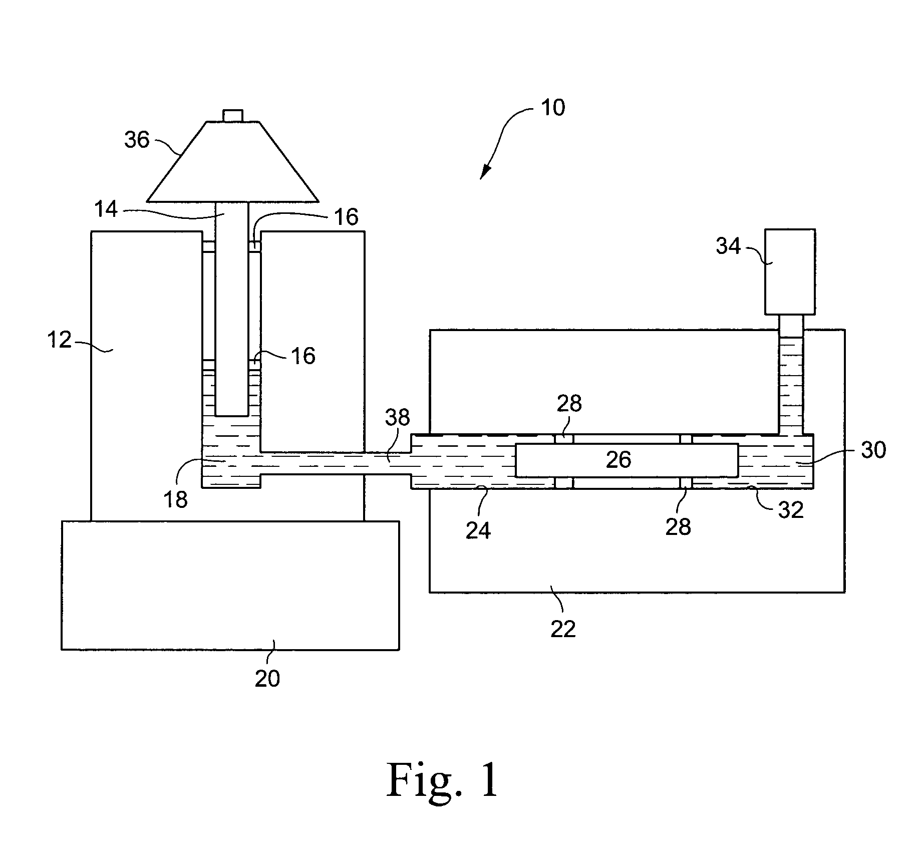
[0005] In accordance with an aspect of the present invention, there is provided a dynamic pressure testing apparatus and methods of dynamic pressure testing wherein the testing may be conducted at a significant range of frequencies, particularly high frequencies, with the article undergoing tests also being simultaneously subjected to caustic or corrosive fluids and the stresses caused thereby. In a preferred embodiment, a first cylinder with a piston slidable relative thereto are mounted on a shaker table or other suitable vibration generator whereby pressure pulses are generated in a first fluid in contact with the piston and cylinder. A second stationary housing or cylinder lies in fluid communication with the first fluid and includes a piston movable relative to the stationary housing or cylinder in response to the pressure pulses generated in the first fluid. The article undergoing testing lies in communication with a second fluid, e.g., a caustic or corrosive fluid also in communication with the second piston whereby the pressure pulses generated by the first fluid are transmitted via the second piston and second fluid to the article undergoing testing. With the article in contact with the caustic or corrosive second fluid and being subjected to the pressure pulses of the second fluid, the dynamic pressure testing may proceed at selected frequencies and amplitudes and temperatures limited only by the material of the testing apparatus. Moreover, by varying the mass of the first piston, e.g., by adding or removing mass to the first piston, the amplitudes and resonant frequencies of the generated pressure pulses can be varied as desired. For example, pressures can be generated with this test set-up in a range of 20-200 p.s.i. or higher with frequencies between about 100 Hz to about 400 Hz. A set-up of this type enables dynamic pressure testing using corrosive fluids over a large number of cycles in a limited time frame, e.g., one billion cycles in a matter of weeks and at desired resonant frequencies.

Problems solved by technology

When a differential pressure is applied to the tube sections and the diaphragm ruptures, a resulting pressure shock occurs.
Disadvantages of shock tube dynamic pressure testing include a complexity of and difficulty for setting up the test, is limited to one cycle only, cannot use liquid fluid media during testing and the shock wave raises the gas temperature.
Generators of this type, however, are limited mechanically by the opening of the valve and are unable to reach high frequency pulses, i.e., cycles per second.
Generators of this type, however, are limited to single step response, i.e., one cycle.
Shaker base systems, however, are generally cumbersome, require heavy duty shakers for large pressure displacements, and have their own governing maximum operating temperatures.
While devices of this type are typically used with acoustic sensors such as microphones, pistonphones are limited to low frequencies and amplitudes.
Oftentimes, these dynamic pressure systems cannot meet amplitude and frequency requirements for many applications.
Further, many articles are subjected to caustic or corrosive fluids in use.

Method used


Image

  • Apparatus and methods for dynamically pressure testing an article
  • Apparatus and methods for dynamically pressure testing an article
  • Apparatus and methods for dynamically pressure testing an article

Examples


Embodiment Construction

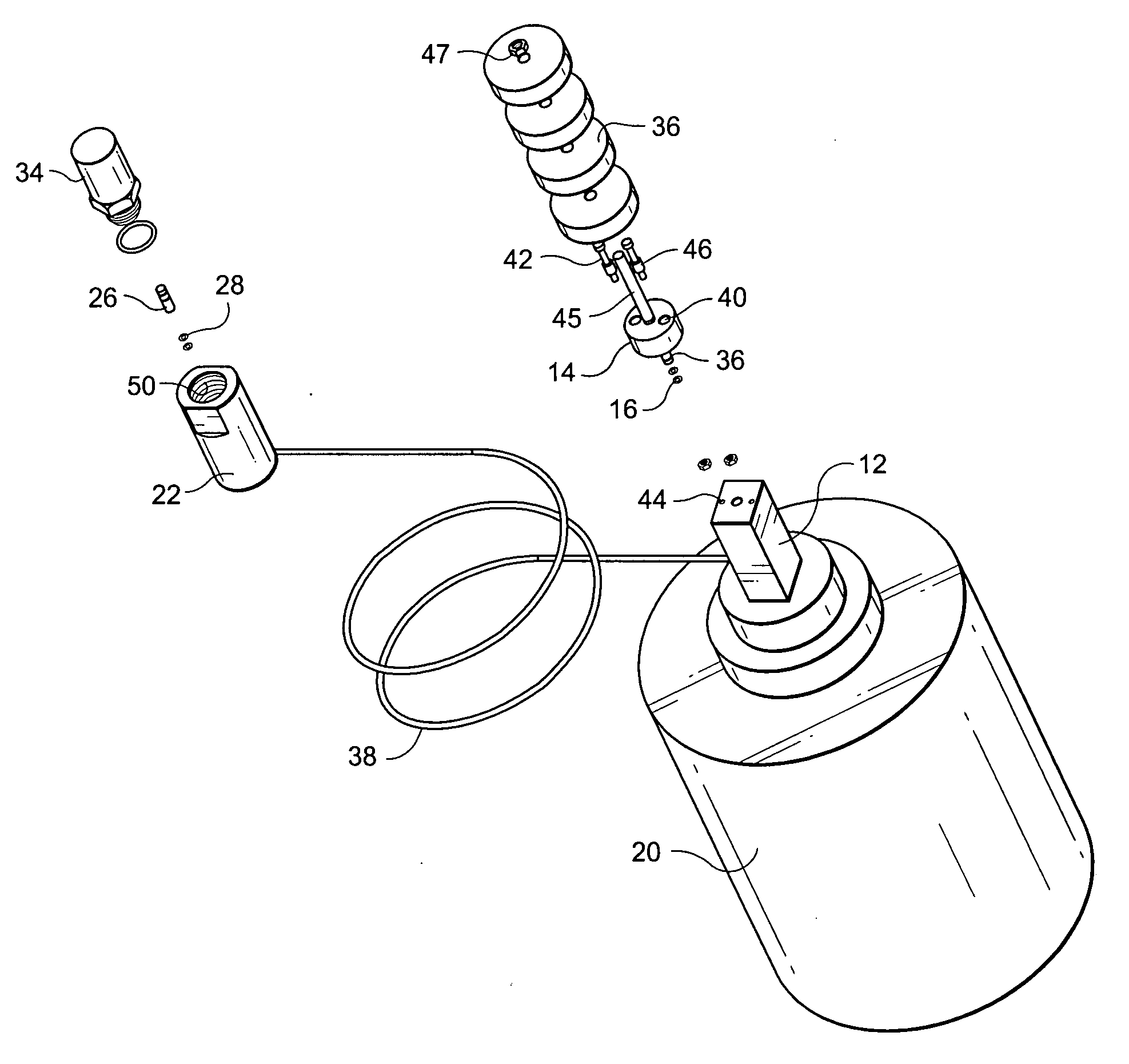
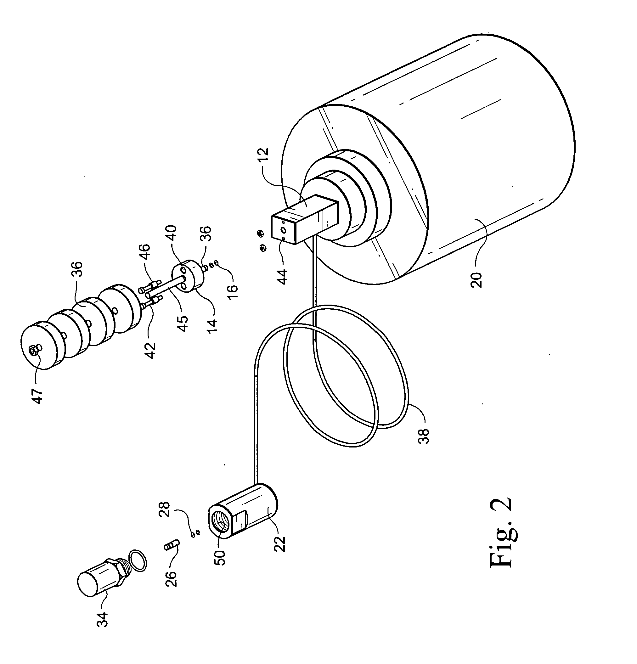
[0013] Referring now to the drawings, particularly to FIG. 1, there is schematically illustrated a dynamic pressure testing apparatus in accordance with a preferred aspect of the present invention and generally designated 10. Apparatus 10 includes a fluid cylinder 12 and a piston 14, the cylinder 12 and piston 14 being oriented vertically. As illustrated, piston 14 is sealed within the cylinder 12 by seals 16 and a fluid 18 is disposed in the cylinder 12 below piston 14. The cylinder 12 is preferably disposed on a shaker table 20. Shaker table 20 may comprise a conventional shaker table, e.g., a shaker table identified as M&B Dynamics Cal 50, and preferably vibrates in a vertically oriented direction, enabling vibration of the cylinder 12 secured to the shaker table. It will be appreciated that any other suitable conventional apparatus for generating vibration may be used in lieu of a shaker table.

[0014] Apparatus 10 also includes a housing 22 carrying or forming a part of a second...


PUM


Abstract

The dynamic pressure tester includes a first cylinder and a first piston movable relative to the cylinder. The piston may have one or more weights applied thereto. The cylinder is vibrated by a shaker table and pressure pulses in the fluid are transmitted to a stationary housing and to a second piston in the housing. The opposite side of the piston contacts a corrosive or caustic fluid also in contact with the sensor face of an article being tested. The pressure pulses are transmitted by the second piston and corrosive fluid to the sensor face, enabling dynamic pressure testing in the corrosive fluid.

Description

[0001] The present invention relates to apparatus and methods for dynamically pressure testing an article and particularly relates to testing apparatus and methods for simulating dynamic pressure on an article exposed to caustic or corrosive fluids in practical applications of the article. BACKGROUND OF THE INVENTION [0002] Dynamic pressure testing of articles, for example, pressure transducers for use in various applications is well known. Dynamic pressure testing is typically used to test the longevity of an article, e.g., a pressure transducer when subjected to a plurality of time dependent cycles. Many and different types of dynamic pressure testing apparatus have been utilized. For example, shock tube testing provides two sections of a tubing separated by a thin diaphragm. When a differential pressure is applied to the tube sections and the diaphragm ruptures, a resulting pressure shock occurs. Disadvantages of shock tube dynamic pressure testing include a complexity of and dif...

Claims


Application Information

Patent Timeline
IPC IPC(8): G01L7/00G01N17/00G01L7/16G01L27/00G01M3/02G01N3/00G01N3/02G01N3/12G01N3/32G01N3/34G01N3/36
CPCG01N3/12G01N3/36G01N2203/0005G01L27/005G01N2203/0073G01N2203/023G01N2203/024G01N2203/0048
Inventor BELL, ANDREWMCMILLEN, CHRISTOPHER
Owner GENERAL ELECTRIC CO
Learn More