Constant contact side bearing assembly for a railcar

a bearing assembly and railcar technology, applied in the direction of bearings, shafts and bearings, rotary bearings, etc., can solve the problems of railcar trucks also prone to oscillate or “hunt”, and the car body tends to adversely roll from side to side,

a bearing assembly and railcar technology, applied in the direction of bearings, shafts and bearings, rotary bearings, etc., can solve the problems of railcar trucks also prone to oscillate or “hunt”, and the car body tends to adversely roll from side to side,

US20050183626A1Active Publication Date: 2005-08-25MINER ENTERPRISES INC

Image

  • Constant contact side bearing assembly for a railcar
  • Constant contact side bearing assembly for a railcar
  • Constant contact side bearing assembly for a railcar

Examples


Embodiment Construction

[0037] While the present invention is susceptible of embodiment in multiple forms, there is shown in the drawings and will be described a preferred embodiment of the invention, with the understanding the present disclosure sets forth an exemplification of the invention which is not intended to limit the invention to the specific embodiment illustrated and described.

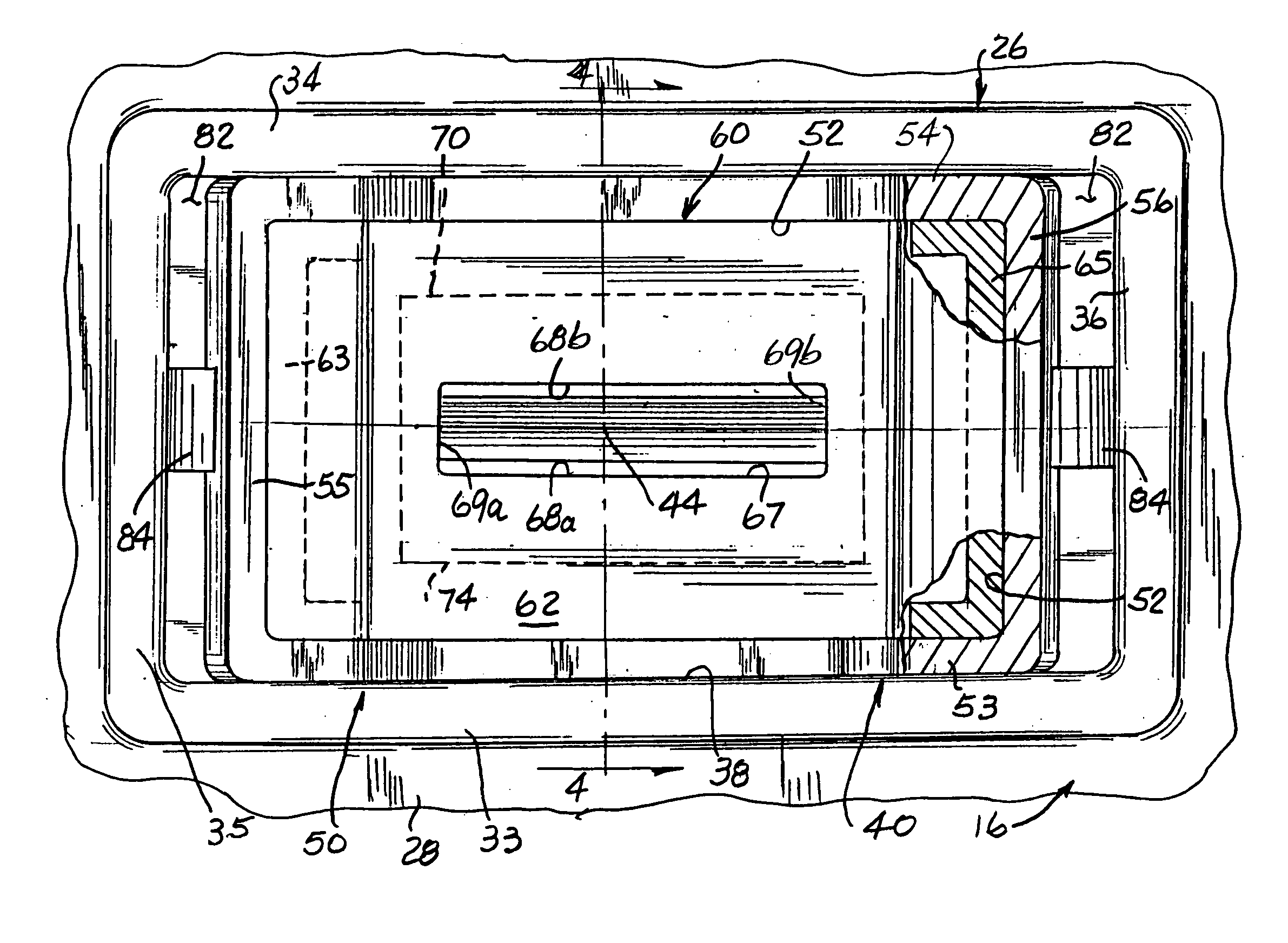
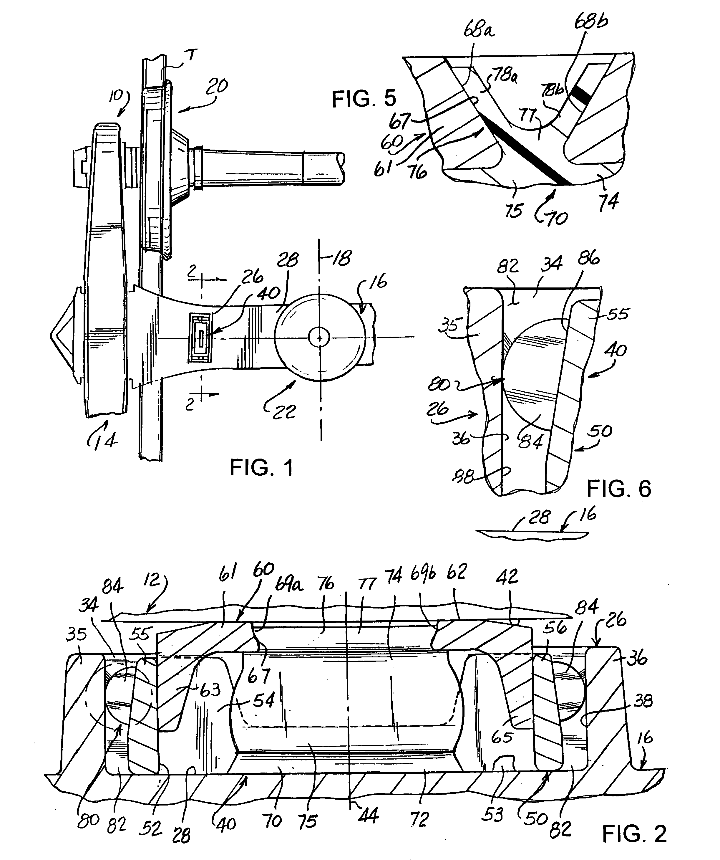
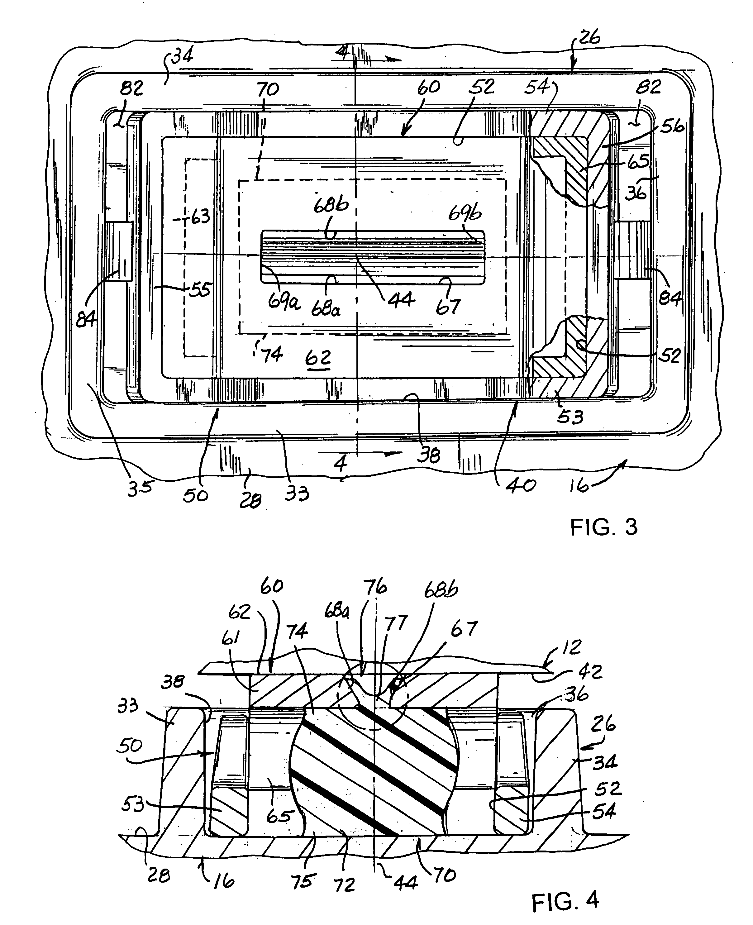
[0038] Referring now to the drawings, wherein like reference numerals indicate like parts throughout the several views, there is shown in FIG. 1 a fragment of a railcar wheeled truck assembly, generally indicated by reference numeral 10, which supports and allows a railcar body 12 (FIG. 2) to ride along and over tracks T. Truck assembly 10 is of a conventional design and includes a side frame 14, a bolster 16, extending generally transversely relative to a longitudinal centerline 18 of the railcar body 12, and a wheel set 20. A conventional center bearing plate 22 is suitably mounted on the bolster 16 for pivotally suppo...


PUM


Abstract

A constant contact side bearing assembly configured for insertion into a walled receptacle provided on an upper surface of a railcar bolster. The constant contact side bearing assembly includes a walled housing defining a cavity extending therethrough and open at opposite ends and a spring having a first end, abuttingly engaging a portion of the upper surface of said railcar bolster, and a second end, axially spaced from the first end. A cap is arranged at the second end of the spring. The cap is mounted for reciprocatory guided movements by and relative to the housing, with a generally flat railcar body engaging portion on the cap being positioned relative to the housing and the walled enclosure by the spring. The side bearing assembly further includes an apparatus for locating and securing the side bearing assembly within the walled receptacle on the railcar bolster.

Description

FIELD OF THE INVENTION [0001] The present invention generally relates to railcars and, more particularly, to a constant contact side bearing assembly for a railcar. BACKGROUND OF THE INVENTION [0002] On a railcar, wheeled trucks are provided toward and support opposite ends of a railcar body for movement over tracks. Each truck includes a bolster extending essentially transversely of the car body longitudinal centerline for supporting the railcar body. In the preponderance of freight cars, a pivotal connection is established between the bolster and railcar body by center bearing plates and bowls transversely centered on the car body underframe and the truck bolster. Accordingly, the truck is permitted to pivot on the center bearing plate under the car body. As the railcar moves between locations, the car body tends to adversely roll from side to side. [0003] Attempts have been made to control the adverse roll of the railcar body through use of side bearings positioned on the truck b...

Claims


Application Information

Patent Timeline
25 Aug 2005
Publication
US20050183626A1
IPC
B61F5/14
CPC
B61F5/142
Inventors
O'DONNELL, WILLIAM P.; ASPENGREN, PAUL B.