Recording tape cartridge

Active Publication Date: 2005-08-25
FUJIFILM CORP +1
View PDF26 Cites 14 Cited by
  • Summary
  • Abstract
  • Description
  • Claims
  • Application Information

AI Technical Summary

Benefits of technology

[0015] It is an object of the present invention to obtain a recording tape cartridge which, even when incorporating a lock mechanism that can render the reel immovable in the axial direction thereof when the recording tape cartridge is not in use, can ensure that the assembly of the case is not compromised.

Problems solved by technology

There has been the problem that if the recording tape cartridge is loaded into the drive device in this state, recording and playback are impossible, and the potential arises for the recording tape cartridge to sustain damage and for the drive device to break down.
There has also been the problem that the recording tape may be adversely affected, such as the recording tape becoming wrinkled or breaking, because the reel is rotatable when the recording tape cartridge is not in use.
Also, because the distance between the upper flange and the lower flange of the reel is substantially the same as the width of the recording tape, when the reel wobbles inside the case and the outer peripheral edges of the upper flange and lower flange strike the inner surface of the case and are deformed as a result of accidentally dropping the recording tape cartridge, there has been the problem that the recording tape is adversely affected, resulting in, for example, kinks in the recording tape.
Thus, when a lock mechanism is disposed on the inner surface of the top plate, there is the potential for the parts configuring the lock mechanism to fall out at the time the case is assembled.
In other words, it is necessary to improve the incorporability of the lock mechanism in the case, and devices for this purpose have conventionally been a problem.

Method used


Image

  • Recording tape cartridge
  • Recording tape cartridge
  • Recording tape cartridge

Examples


Embodiment Construction

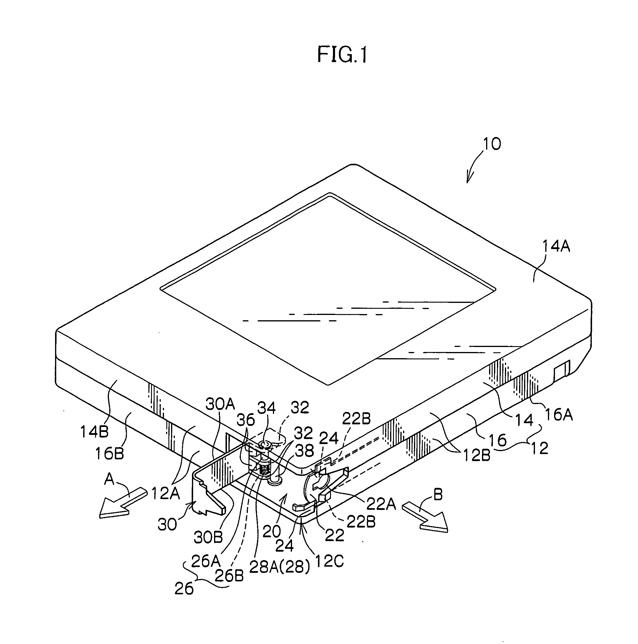
[0049] An embodiment of the invention will be described in detail below on the basis of examples showing in the drawings. For convenience of explanation, the direction in which the recording tape cartridge is loaded into a drive device will be represented by arrow A and referred to as the front direction of the recording tape cartridge. Arrow B will represent a left direction, and expressions such as front / rear, left / right and up / down will be given on the basis of these directions. When “radial direction” is used in the following description, this will indicate a direction parallel to directions facing radially outward from an axial center (core) of a reel housed in a case.

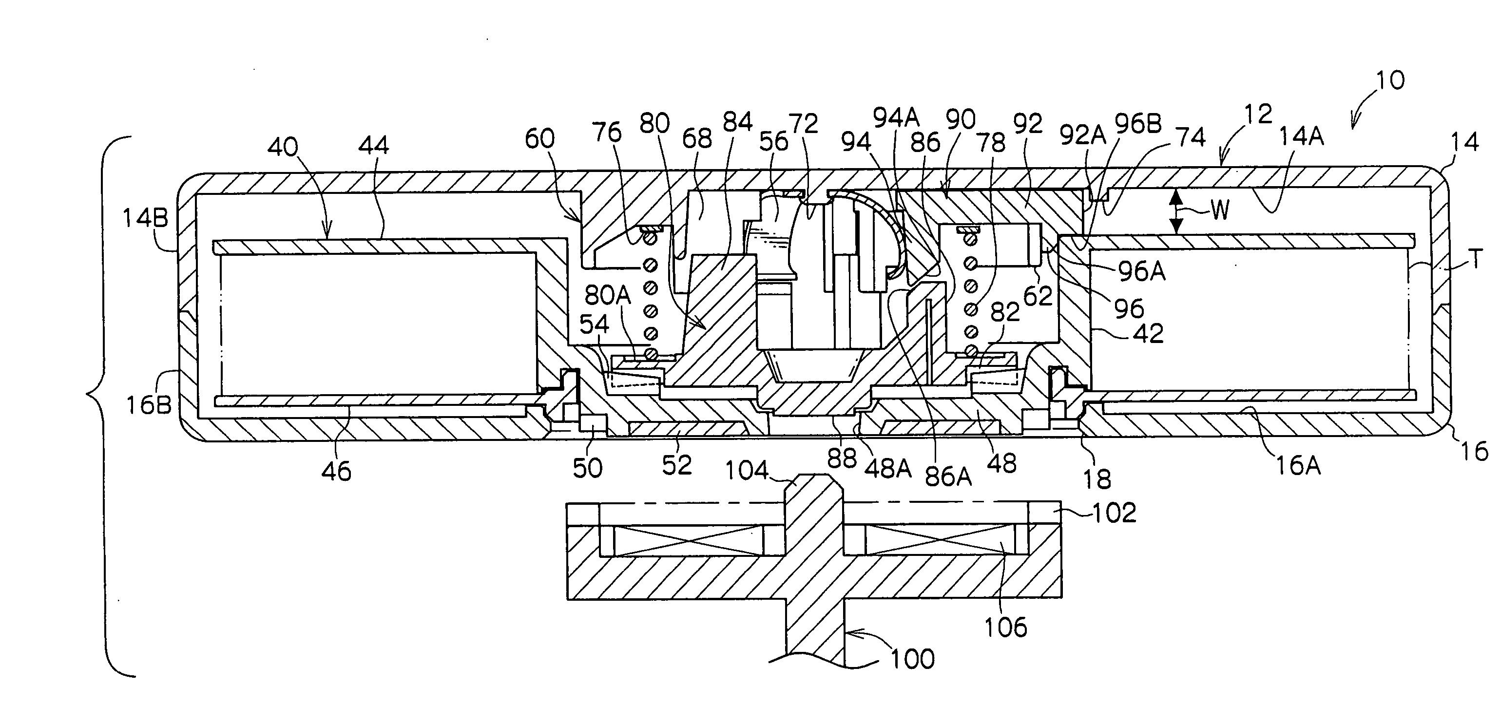
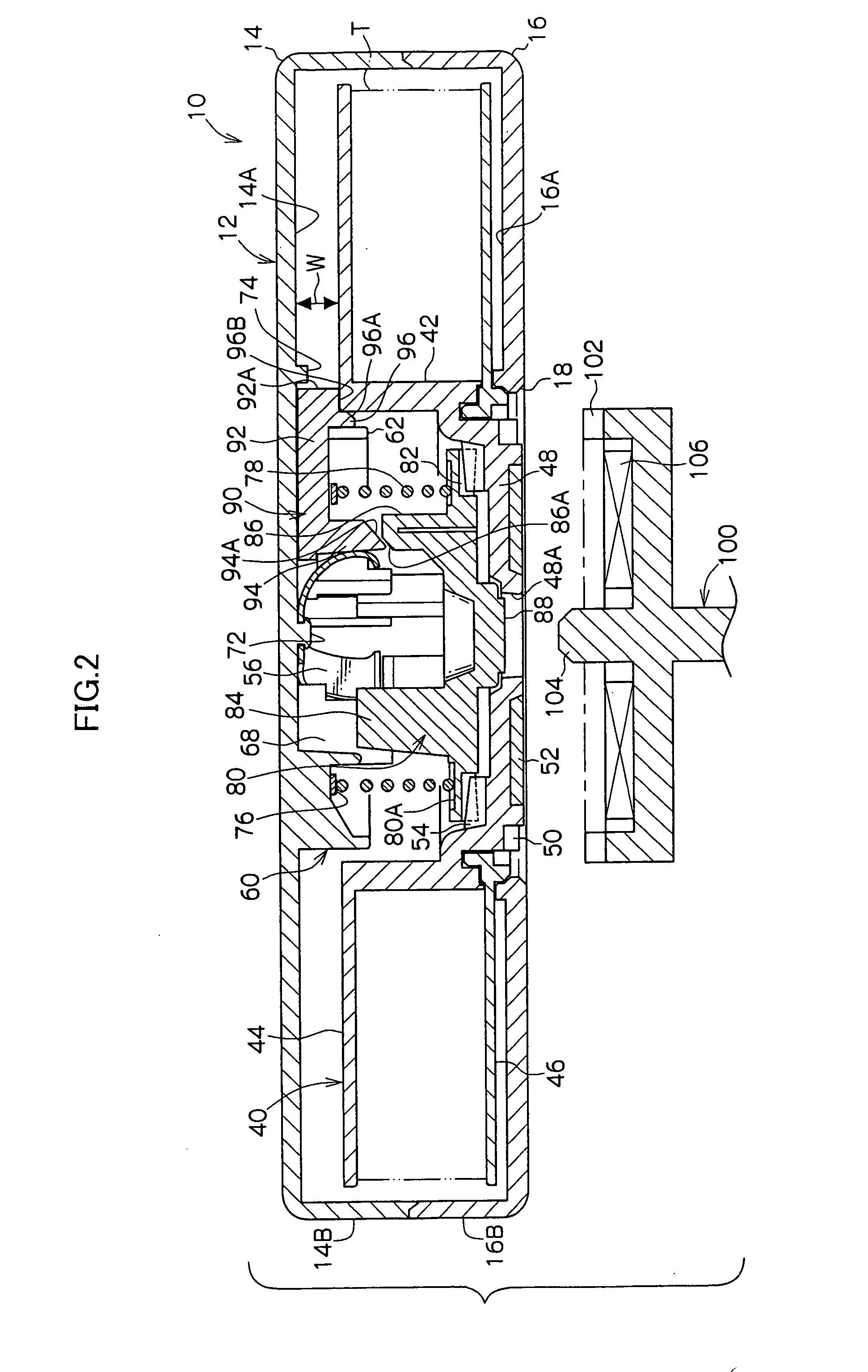
[0050] As shown in FIG. 1, a recording tape cartridge 10 includes a case 12, which has a substantially rectangular box-like shape. The case 12 includes an upper case 14 and a lower case 16 that are made of a resin such as PC. The upper case 14 includes a peripheral wall 14B vertically disposed at the peripheral e...


PUM


Abstract

A recording tape cartridge (10) includes: a case (12) that houses a reel (40) onto which a recording tape is wound, the case comprising an upper case (14) including a top plate (14A) and a lower case (16) including a bottom plate (16A); lock members (90) that are disposed, so as to be slidable in a radial direction of the reel, in an attachment portion (60) formed on an inner surface of the top plate, the lock members being movable between a rise / fall lock position, at which the lock members are intervened between an upper surface of the reel and the top plate to prevent movement in an axial direction of the reel, and a rise / fall allowance position, at which the lock members are retracted from between the upper surface of the reel and the top plate to allow movement in the axial direction of the reel; and projecting portions (70A) that are formed on the inner surface of the top plate and project towards the lock members so that the lock members do not fall out of the attachment portion at least when the case is assembled.

Description

CROSS-REFERENCE TO RELATED APPLICATION [0001] This application claims priority under 35 USC 119 from Japanese Patent Application No. 2004-048566, the disclosure of which is incorporated by reference herein. BACKGROUND OF THE INVENTION [0002] 1. Field of the Invention [0003] The present invention relates to a recording tape cartridge including a case that houses a single reel onto which is wound a recording tape such as magnetic tape mainly used as a recording and playback medium for computers and the like. [0004] 2. Description of the Related Art [0005] Conventionally, a recording tape cartridge has been known which includes a case that is made of synthetic resin and rotatably houses a single reel onto which is wound a recording tape such as magnetic tape used as a recording and playback medium for computers and the like. When the recording tape cartridge is in use (i.e., when it has been loaded into a drive device), the reel of the recording tape cartridge is rotatable within the c...

Claims


Application Information

Patent Timeline
IPC IPC(8): G11B23/04G11B23/07G11B23/107G11B23/28
CPCG11B23/043
Inventor HIRAGUCHI, KAZUO
Owner FUJIFILM CORP
Why Eureka
Try Eureka