CCFL illuminated device and method of use

a fluorescent lamp and illumination device technology, applied in the field of miniature cold cathode fluorescent lamps, can solve the problem of very low light outpu

Inactive Publication Date: 2005-08-25
T 1 LIGHTING
View PDF5 Cites 96 Cited by
  • Summary
  • Abstract
  • Description
  • Claims
  • Application Information

AI Technical Summary

Benefits of technology

[0018] In an alternative embodiment, one or more cold cathode fluorescent lamps (CCFLs) are enclosed in a single tubular housing which, preferably, is a conventional T-5 fluorescent bulb with a conventional bi-pin connection at each end. In this embodiment, the electrodes at each end of the CCFLs can be connected i...

Problems solved by technology

Also, they may be dimmed to...

Method used


Image

  • CCFL illuminated device and method of use
  • CCFL illuminated device and method of use
  • CCFL illuminated device and method of use

Examples


Embodiment Construction

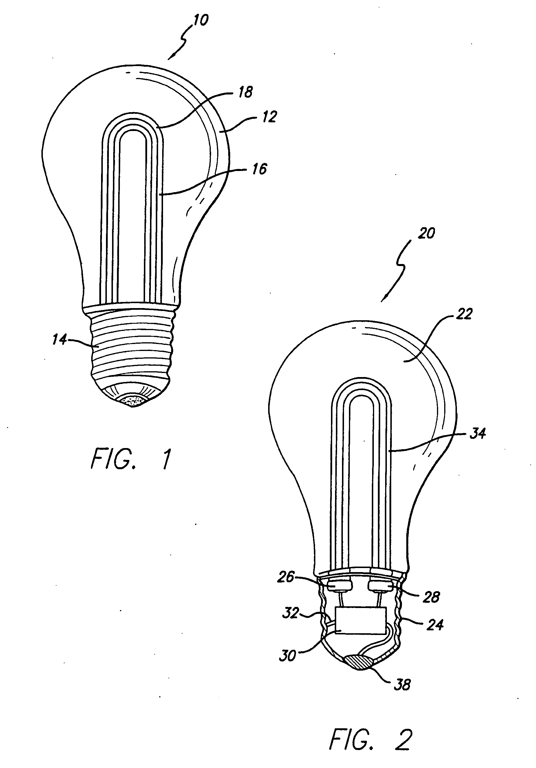
[0025]FIG. 1 is a perspective view of an A-lamp light bulb 10 of the present invention. The A-lamp shape is well known and the electrode configuration with the socket is well known. Thus, by providing the same shape bulb or envelope portion 12, the present invention will be immediately useful wherever common incandescent bulbs are used. The base portion 14 is the same size and shape as the common incandescent bulb socket portion. The CCFL lamp 16 has a single U-shaped bend in the middle. A plurality of bends or CCFL lamps of different geometries would also be within the scope of the present invention and would be known to those skilled in the art. It will also be understood that a tubular housing 18 may or may not be necessary or desirable, depending upon the end use of the bulbs and the environment in which it is to operate.

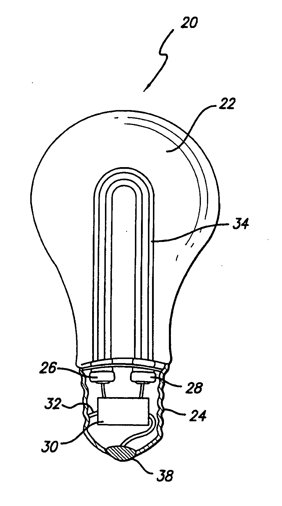
[0026]FIG. 2 is a cross section of an A-lamp light bulb 20 with a CCFL device, associated electronics and internal mounting means of the present invention. In ...


PUM


Abstract

A Cold Cathode Fluorescent Lamp (CCFL) is enclosed within a bulb normally used for incandescent fixtures. The CCFL is bent into a u-shape to fit within the bulb and the ballast can be installed in the lamp base. In an alternative embodiment, one or more CCFLs is enclosed within a fluorescent lamp tube or bulb with bi pin end caps. An insert in the end cap can support the CCFLs. Contact is made to the CCFLs through a connection with the pins of the end caps. In an alternative arrangement, the CCFLs are supported within the tube by electrode wires connecting to the pins.

Description

[0001] This is a continuation-in-part of U.S. patent application Ser. No. 10 / 414,714, which is a continuation of U.S. patent application Ser. No. 09 / 598,009, filed Jun. 20, 2000, which is a continuation-in-part of U.S. patent application Ser. No. 08 / 630,161 filed Apr. 10, 1996, now U.S. Pat. No. 6,135,620, issued Oct. 24, 2000.FIELD OF INVENTION [0002] This invention relates generally to miniature cold cathode fluorescent lamps (CCFLs) and other miniature fluorescent lamps, associated devices and methods of use, and more specifically, to lighting devices utilizing CCFL-type devices in conjunction with novel connectors, mounting brackets, housings and other accessories to provide new and unique lighting devices and methods of using them, all of which offer significant savings in cost, operating expense, power consumption and retrofit convenience. BACKGROUND OF THE INVENTION [0003] Electrically powered exit signs, traffic signals, task lights and other devices are widely used. Fluores...

Claims


Application Information

Patent Timeline
IPC IPC(8): B01F7/00B01F7/08B01F13/00B01F13/10B01F15/00F21V15/00F21V17/04G09F13/04G09F13/26H01J5/48
CPCF21V17/04F21Y2103/00H01J5/48G09F13/26G09F13/04
Inventor STURMAN, BRUCE D.MURRAY, IAN C.
Owner T 1 LIGHTING
Why Eureka
Try Eureka