

Recording disk drive capable of reducing vibration within enclosure
a technology of recording disk drive and enclosure, which is applied in the field of clamping, can solve the problems that the alignment cannot be maintained between the rotation shaft and the hub, and achieve the effects of reducing the rigidity of the stator, preventing the effect of receiving, and suppressing the increase of vibration
- Summary
- Abstract
- Description
- Claims
- Application Information
AI Technical Summary
Benefits of technology
Problems solved by technology
Method used
Image

Examples
Embodiment Construction
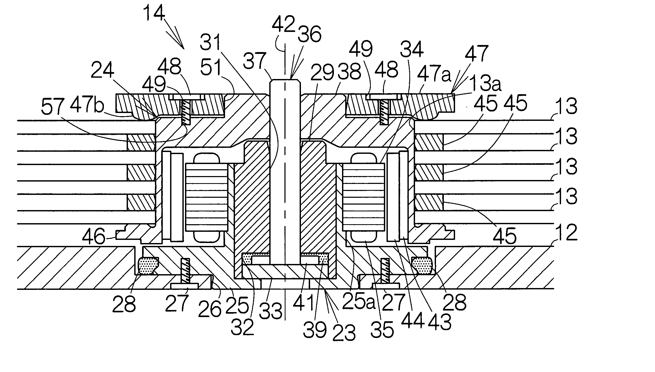
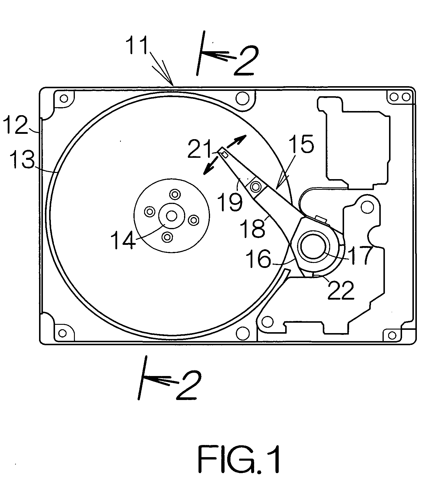
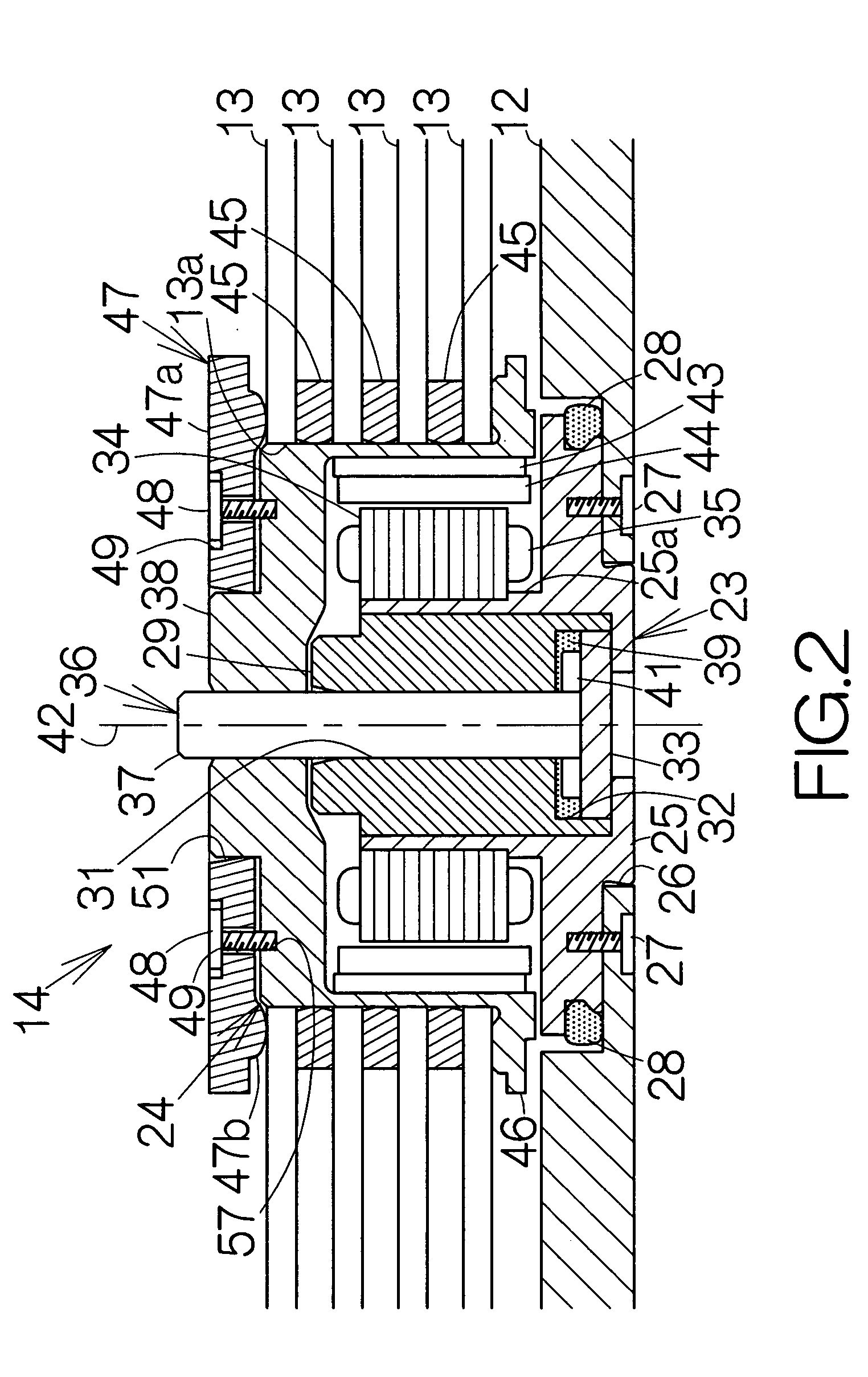
[0036]FIG. 1 schematically illustrates the inner structure of a hard disk drive (HDD) 11 as an example of a recording disk drive or storage device according to an embodiment of the present invention. The HDD 11 includes a box-shaped main enclosure 12 defining an inner space of a flat parallelepiped for example. At least one magnetic recording disk 13 is mounted on the driving shaft of a spindle motor 14 within the main enclosure 12. The spindle motor 14 is allowed to drive the magnetic recording disk 13 for rotation at a higher revolution speed such as 7,200 rpm, 10,000 rpm, 15,000 rpm, or the like, for example. A cover, not shown, is coupled to the main enclosure 12 so as to define the closed inner space between the main enclosure 12 and the cover itself. A packing is interposed between the main enclosure 12 and the cover.
[0037] A head actuator 15 is also accommodated in the inner space of the main enclosure 12. The head actuator 15 comprises an actuator block 16. The actuator blo...
PUM
| Property | Measurement | Unit |
|---|---|---|
| angle | aaaaa | aaaaa |
| angle | aaaaa | aaaaa |
| electric current | aaaaa | aaaaa |
Abstract
Description
Claims
Application Information