Unitary hollowed piston with improved structural strength

Inactive Publication Date: 2005-09-01
DELPHI TECH INC
View PDF10 Cites 2 Cited by
  • Summary
  • Abstract
  • Description
  • Claims
  • Application Information

AI Technical Summary

Benefits of technology

[0012] In the preferred embodiment disclosed, the main body of the piston can be formed by two dies or molds that part in a straight parting line, creating two main outer surface areas, each of which is generally a C shaped, arcuate cross section wall, and minimally thick, and approximately the same length. The C shaped walls each extend over slightly more than 180 degrees, on each side of the piston, providing adequate and well balanced bearing surface within the cylinder. The C shaped walls also overlap in narrow strips of lunate in cross section at the top and bottom, which provides some mutual support between the two walls. The maj

Problems solved by technology

Compressor pistons historically were solid metal cylinders, structurally sound and with more than sufficient outer surface area, but inherently massive.
Just as obviously, this cannot be done in a one piece design.
That is, the lower end of a bottle can be integrally formed, but its lid cannot.
While these are undeniably low mass, with complete outer surface areas, a multi piece design, requiring an extra manufacturing step to join the multiple pieces, is inevitably higher cost than a one piece or unitary design.
These “hollowed out” designs produced many ultimate shapes, most of which were impractical and did not see ultimate production.
Neither design was particularly practical, since one removed too much sides surface area, and the other, while it left a good deal of surface area at least on the critical piston side, left no internal support for the thin, C shaped shell.
However, a drawback of both this design and the first embodiment of Japanese Patent 2924621 is that the wall thickness radially inboard of the piston outer surface area is greater than is ideal.
But, the flat, chordal side of the wall section is what is inevitably left behind by the advancing and retreating forging die or casting mold.
A multi piece design is far less desirable than a one piece design.
However, this is achieved only at the cost of an additional machining step, done after the molding or forging process.
In conclusion, the piston art to date has failed to achieve an ideal combination of one piece, substantially hollow construction with a well distributed outer surface area that is internally well supported, but with minimal wall thickness behind the outer surface area, and which is also formed with a minimum of manufacturing steps.

Method used


Image

  • Unitary hollowed piston with improved structural strength
  • Unitary hollowed piston with improved structural strength
  • Unitary hollowed piston with improved structural strength

Examples


Embodiment Construction

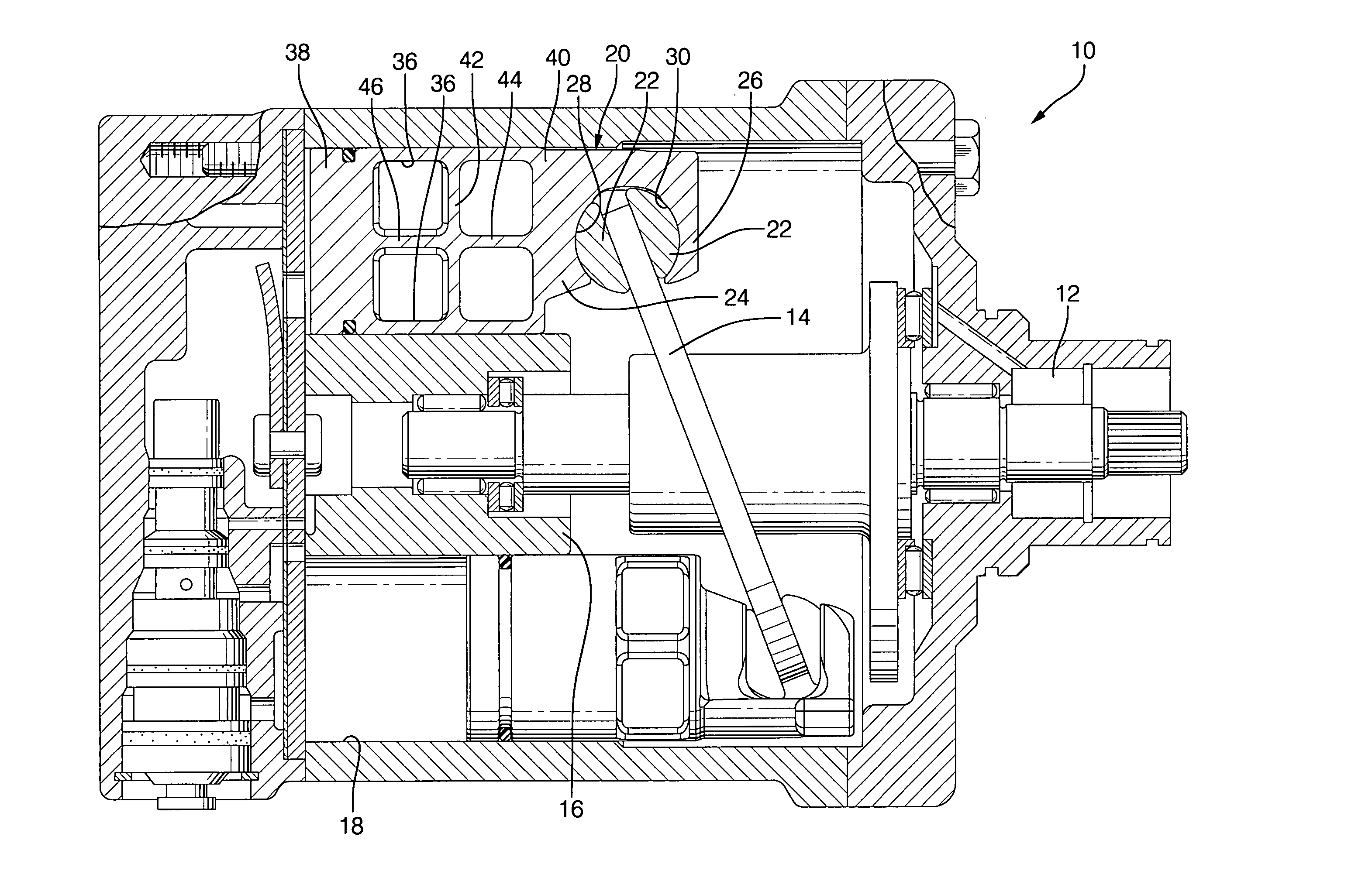
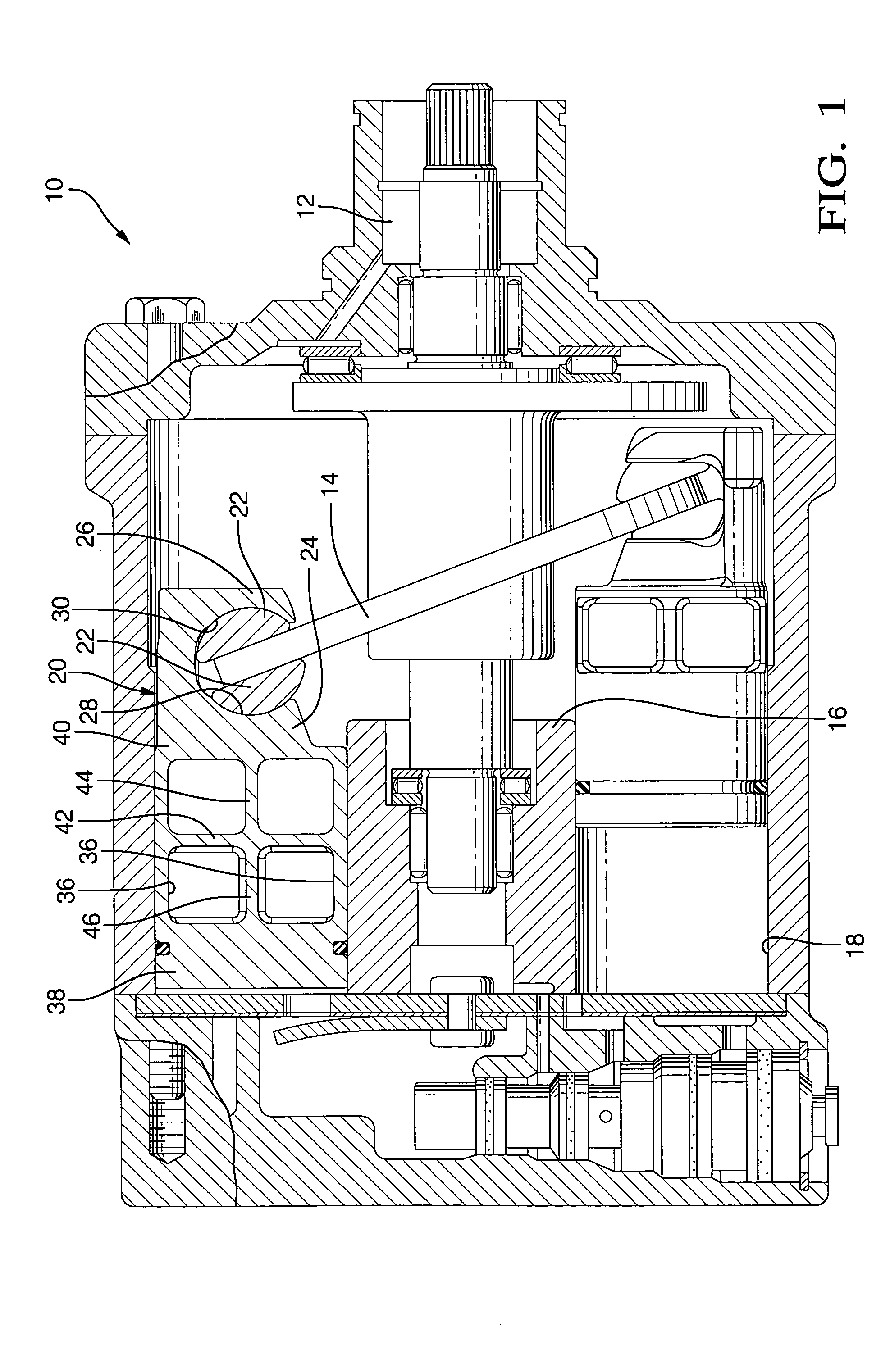
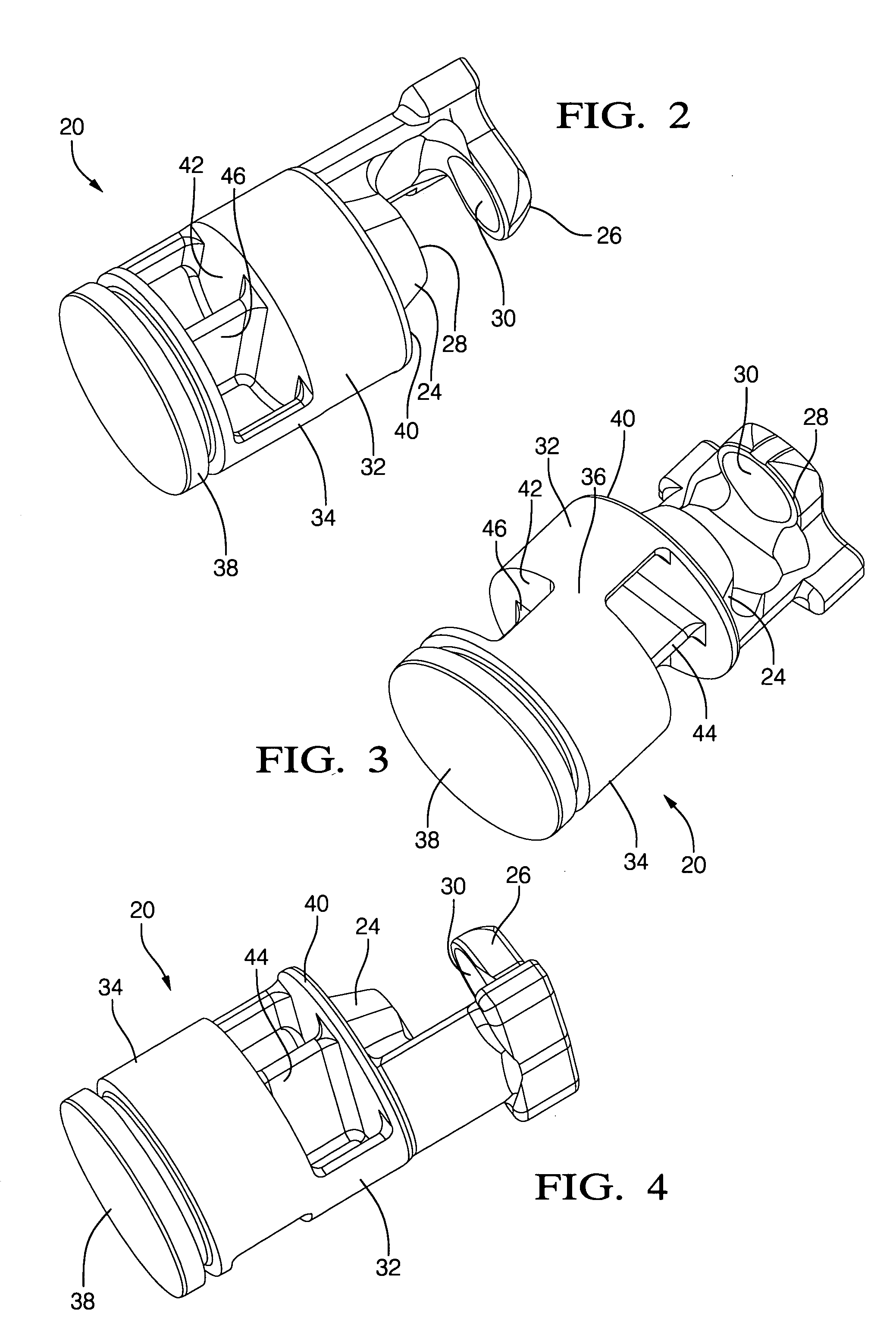
[0021] Referring first to FIG. 1, a compressor 10 has a central driven shaft 12, which rotates a nutating swash or wobble plate 14 within a cast cylinder block 16. Defined within cylinder block 16 are an array of cylinder bores 18, generally 5 to 7 in number. If, for convenience, the piston reference frame described above is oriented with each central plane P including the axis of shaft 12, the in surface of the bore 18 may be considered to have its surface area divided up into corresponding quadrants. A piston, designated generally at 20, is reciprocated axially within each bore 18 by a pair of half ball shoes 22, as the plate 14 slides between the flat sides of the shoes 22. At the rear of each piston 20, a pair of parallel stanchions 24 and 26 contain machined ball sockets 28 and 30, within which the spherical sides of the shoes 22 twist as the plate 14 nutates back and forth on shaft 12. The stanchions 24, 26 and sockets 28, 30 are a standard feature of swash plate driven piston...


PUM


Abstract

A unitary, “hollow out” piston is molded or forged with only two tools, which move along a single parting direction, with a pair of arcuate side walls that provide maximal outer surface area with minimal thickness and weight. The thin walls are internally fortified by a cruciform support structure that is molded integrally by the same tools. No post forming machining steps are needed to reduce weight.

Description

TECHNICAL FIELD [0001] This invention relates to compressor pistons in general, and specifically to a one piece piston, capable of forging or molding (including casting), which maximizes surface area and strength while minimizing mass within the limitations of the method of manufacture. BACKGROUND OF THE INVENTION [0002] Compressor pistons historically were solid metal cylinders, structurally sound and with more than sufficient outer surface area, but inherently massive. Mass could be reduced only by axially shortening the piston, inevitably reducing the outer surface area. Since compressor pistons are typically driven by an inclined swash plate, the reciprocating forces applied to the pistons inevitably have non axial components that act to rock the piston about its axis within the cylinder bore. The outer surface area of the piston is needed to resist these rocking forces, so its outer surface area, ideally, would not be reduced too far from a complete cylinder. [0003] The obvious...

Claims


Application Information

Patent Timeline
IPC IPC(8): F04B27/08
CPCF04B27/0878
Inventor LE, ANHPLEW, ROY ALLANQUESADA, JOHN F.
Owner DELPHI TECH INC
Why Eureka
Try Eureka