Rotary bolt

Inactive Publication Date: 2005-09-01
PLANET ECLIPSE
View PDF36 Cites 26 Cited by
  • Summary
  • Abstract
  • Description
  • Claims
  • Application Information

AI Technical Summary

Benefits of technology

[0015] Yet another object of the present invention is to provide a paintball marker

Problems solved by technology

Pneumatic projectile launcher that use reciprocating bolts suffer several disadvantages that inherently limit the maximum rate of fire achievable.
Second, any interruption in the flow of pro

Method used


Image

  • Rotary bolt
  • Rotary bolt
  • Rotary bolt

Examples


Example

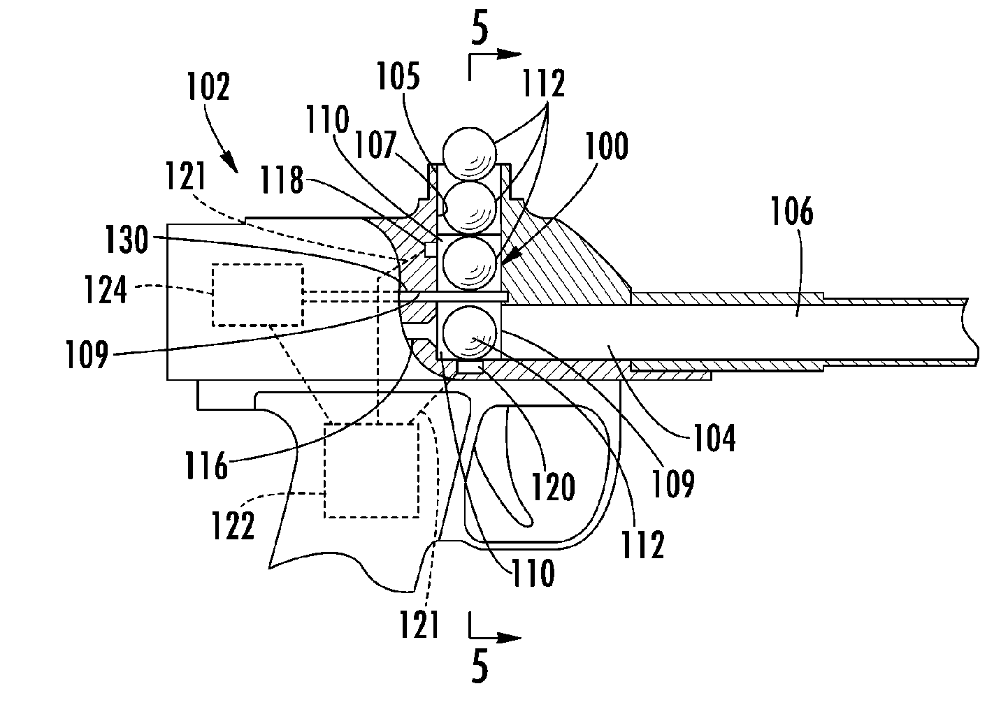
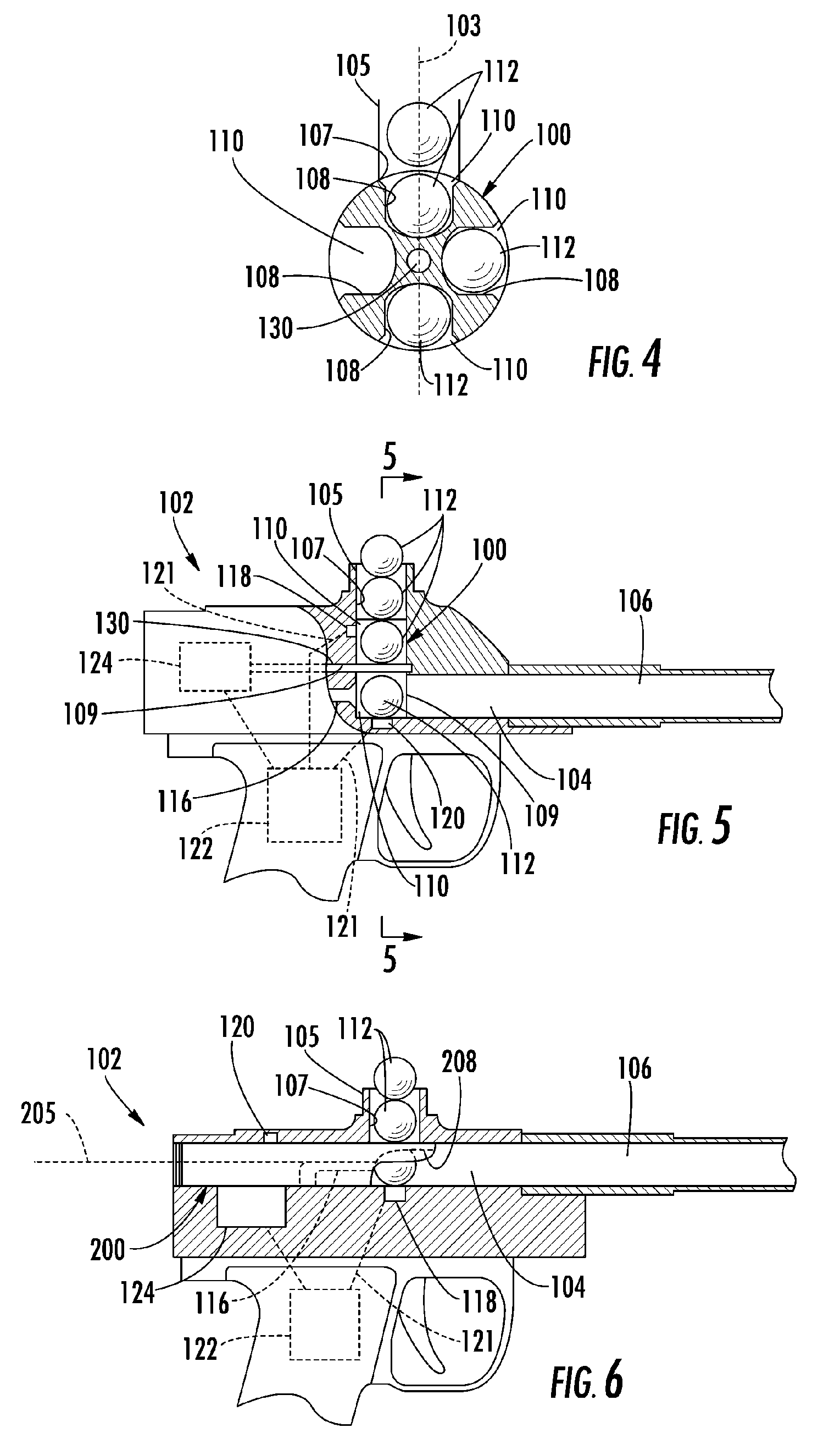
[0023] Referring now to FIGS. 4 and 5, the preferred embodiment of the present invention is shown generally at 100 mounted within a representational projectile launcher 102. The bolt system of the present invention can be used in any projectile launching device. Such devices include paintball markers. For ease of illustration and discussion, the present invention is shown in a paintball marker; however, the invention is intended to cover use in any type of projectile launching device.

[0024] The projectile launcher 102, such as a paintball marker, has a central breech 104. Extending from the breech 104 is the barrel 106. A feed conduit 105 leads to the breech 104 of the paintball marker 102 forming a feed aperture 107. A hopper (not shown) can also be used to gravity feed paintball projectiles 112 into the feed aperture 107. Projectiles 112 flow down the feed conduit 105 and out the feed aperture 107. The rotary bolt 100 of the present invention receives the projectile 112 from the ...


PUM


Abstract

The rotary bolt (100) of the present invention has a cylindrical-shaped bolt assembly, which rotates about a central shaft 130. About the circumference of the bolt (100) are a number of chambers (110), each of which can accept a single projectile (112) as it passes through a feed aperture (107). As the bolt (100) rotates, it transports the projectiles (112) from the feed aperture (107) to the breech (104) from where the projectile (112) can be launched from the barrel (106) of the launching device (102).

Description

CROSS-REFERENCE TO RELATED APPLICATION [0001] This application claims priority to earlier filed U.S. Provisional Application Ser. No. 60 / 545,399, filed Feb. 17, 2004, the contents of which are incorporated herein by reference.BACKGROUND OF THE INVENTION [0002] 1. Field of the Invention [0003] The present invention relates generally to firing mechanisms for pneumatically operated projectile launchers and more particularly to a rotary bolt mechanism for a pneumatically operated projectile launcher. [0004] 2. Description of the Related Art [0005] Referring first to FIG. 1, in a prior art pneumatically or electromagnetically operated projectile launcher 10, projectiles 12 are loaded in to the breech 14 or barrel 16 of the pneumatic projectile launcher 10 by means of a reciprocating bolt 18, which moves back and forth below a feed aperture 20 through which projectiles 12 can pass. A typical projectile that is launched is a paintball, which is well known in the art. FIG. 1 shows a cross-s...

Claims


Application Information

Patent Timeline
IPC IPC(8): F41B11/02
CPCF41B11/50
Inventor MONKS, STEVEN JOHN
Owner PLANET ECLIPSE
Why Eureka
Try Eureka