

Antenna structure and television receiver
a technology of antenna structure and television receiver, which is applied in the direction of resonant antenna, elongated active element feed, television system, etc., can solve the problems of inconvenient carrying about the transmission apparatus, inability to change the directivity of inverted f antennas and loop antennas, and the bulkiness of antennas ruins portability and appearance, so as to improve the portability and appearance of the television receiver.
- Summary
- Abstract
- Description
- Claims
- Application Information
AI Technical Summary
Benefits of technology
Problems solved by technology
Method used
Image

Examples
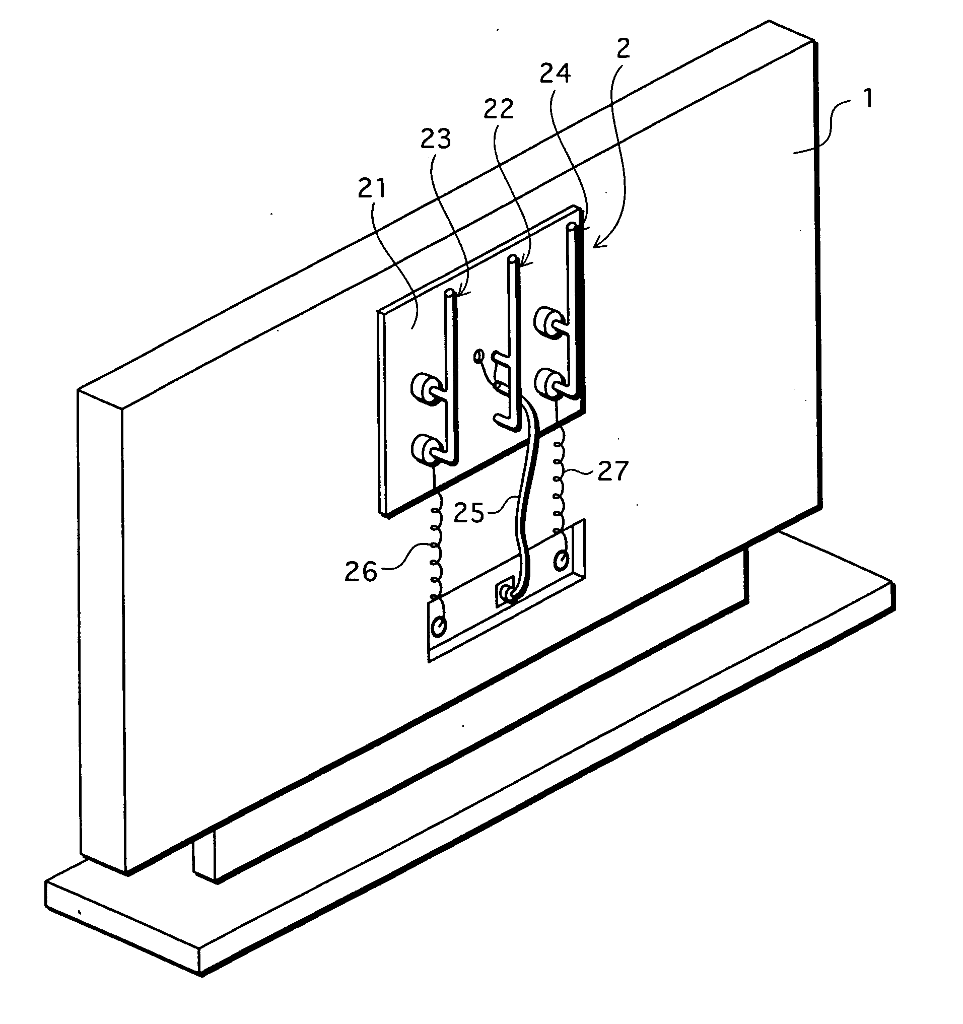
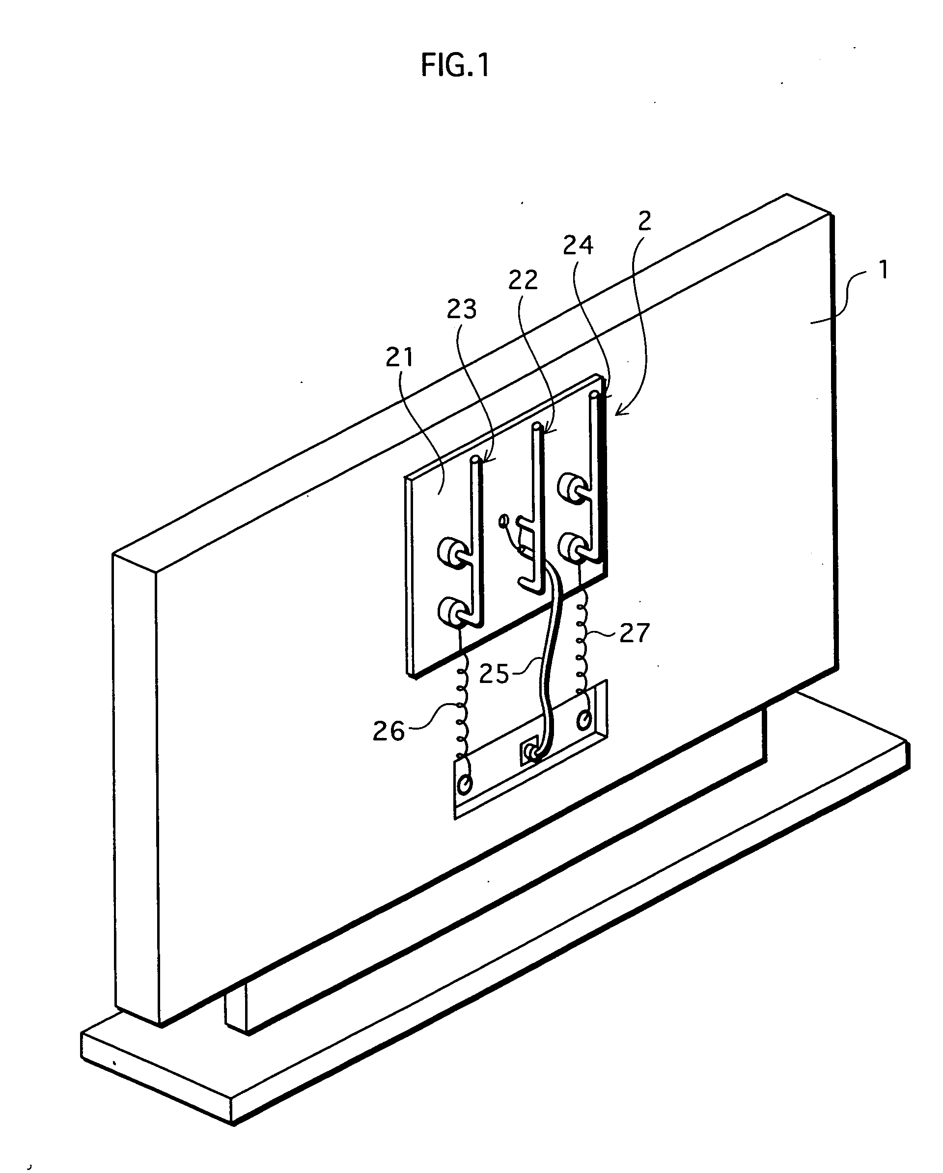
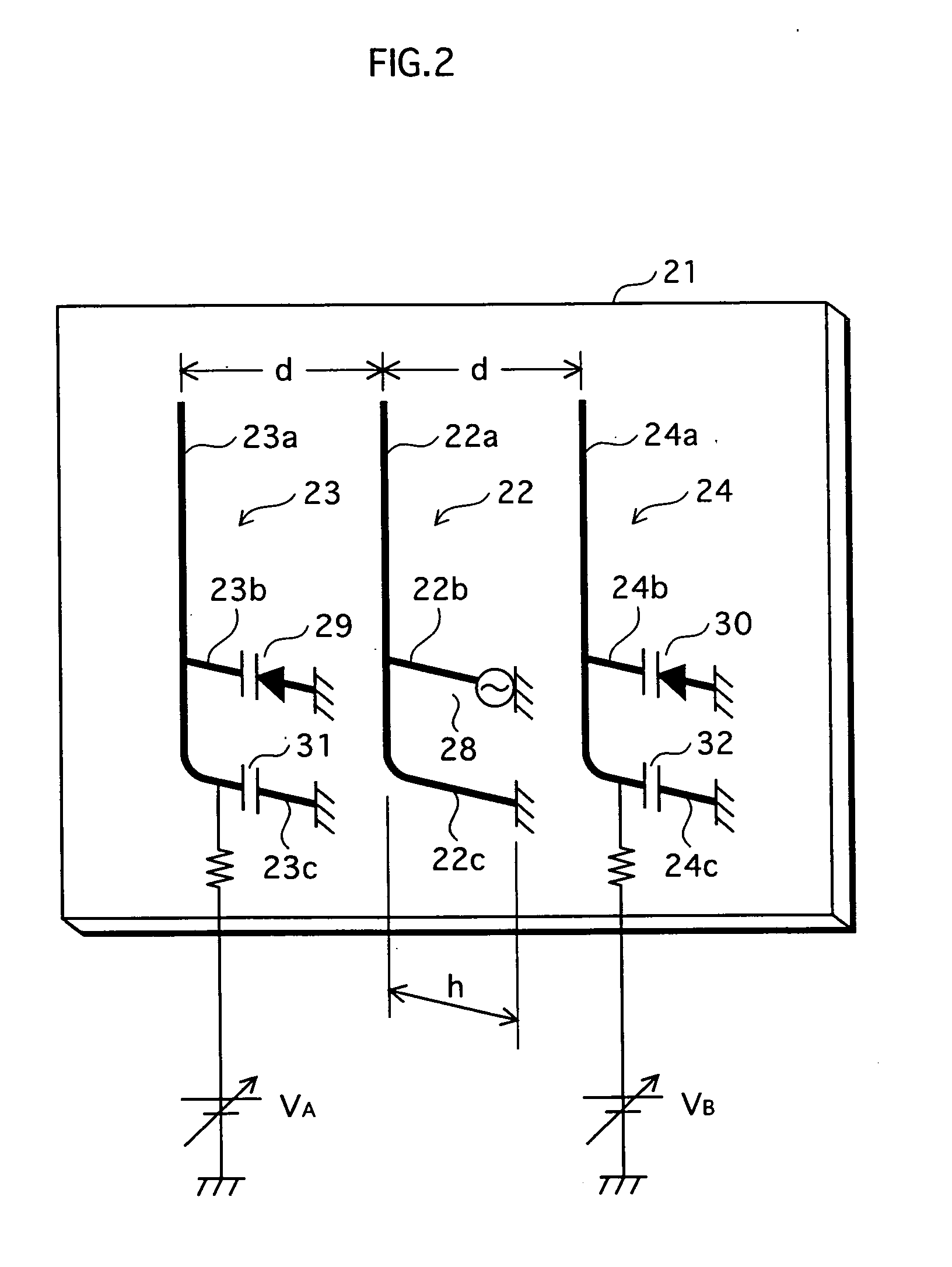
first embodiment
Modified Examples of First Embodiment
[0044] The following describes modified examples of the first embodiment, which are substantially the sameas the first embodiment in structure, but different in detail.
[0045]FIG. 4 illustrates a modified example of the antenna structure according to the first embodiment.
[0046] (1) As shown in FIG. 4, a feedthrough capacitor 33 is inserted in the earth plate 21, instead of providing the capacitor 31 (32) inserted in the second short conductor of the passive element 23 (24).
[0047] By this, the antenna structure can be simplified because it is not necessary to ground an end of the second short conductor to the earth plate and to insert the capacitor in the second short conductor.
[0048]FIG. 5 illustrates a modified example 2 of the antenna structure according to the first embodiment.
[0049] (2) In the first embodiment, one end of each of the long conductors 22a, 23a, and 24a is an open end. In the modified example 2, an end section of the long co...
second embodiment
Modified Examples of Second Embodiment
[0061]FIG. 9 illustrates a modified example of the antenna structure according to the second embodiment.
[0062] (1) FIG. 9 illustrates one of the passive elements. The total length of the passive element is nλ / 4, and one end of the passive element is an open end. Although the feed element is not depicted in the drawing, the feed element of the first modified example of the second embodiment is substantially in the same structure as the passive element illustrated by FIG. 9, other than that the feed element includes the feeding point, instead of the varicap diode.
[0063] The above structure in which the antenna length is half as long as the length of the elements of the second embodiment and an open end is included is also equivalent to the elements of the second embodiment, as can be understood by the so-called electric image method.
[0064]FIG. 10 illustrates another modified example of the antenna structure according to the second embodiment.
[...
third embodiment
[0066]FIG. 11 is a diagram to explain basics of an antenna structure according to a third embodiment.
[0067] As shown in FIG. 11, a difference from the other embodiments here lies in that a feed element 62 is of a twin-inverted F type and passive elements 63 and 64 are of a twin-inverted L type. An actual shape of the element is similar to a bottom part of the elements shown in FIG. 10 after an upper part of the long conductors is cut at the middle of the long conductors where the current flows through the loop becomes almost 0. Therefore, a current distribution and impedance in this embodiment is equivalent to the example shown in FIG. 10. In that regard, the twin-inverted F type and twin-inverted L type can be included in variations of the loop type.
[0068] The feed element 62 is of the inverted F type as in the case of the first embodiment. FIG. 11 also shows holding members 68 for holding the feed element 62 and passive elements 63 and 64 with an adequate distance from a wall 69...
PUM
 Abstract
Description
Claims
Application Information