Imaging device and image generation method of imaging device

a technology of imaging device and image, which is applied in the direction of color television signal processing, television system scanning details, television system, etc., can solve the problems of mechanical shutter drive having a limit to perform a continuous capturing at unlimited high, distortion of images may not be permitted, and the image top and bottom image is affected

Inactive Publication Date: 2005-09-01
KYOCERA CORP
View PDF7 Cites 126 Cited by
  • Summary
  • Abstract
  • Description
  • Claims
  • Application Information

AI Technical Summary

Benefits of technology

[0047] According to a second aspect of the present invention, there is provided An image generation method of an imaging device performing predetermined image processing for image data read out from an imaging element having steps of reading out high image data having high-resolution or low image data having low-resolution from the imaging element by making an optical image of a subject to form on the imaging element, generating a first compressed image by compressing the high image data with intra-frame compression in

Problems solved by technology

Here, in capturing an image by only the rolling shutter, distortion of the image occurs in the top and the bottom of the image.
However, when capturing the still images, the distortion of the images may not be permitted.
Therefore, the mechanical shutter and the global shutter become necessary, however, the mechanical shutter drive has a limit to perform a continuous capturing at unlimitedly high speed.
However, when capturing image having high-resolution by, for example, several scenes at a second for ten seconds, the recorded image data becomes enormous and it has little practicability in considering capacity of a memory car

Method used


Image

  • Imaging device and image generation method of imaging device
  • Imaging device and image generation method of imaging device
  • Imaging device and image generation method of imaging device

Examples


first embodiment

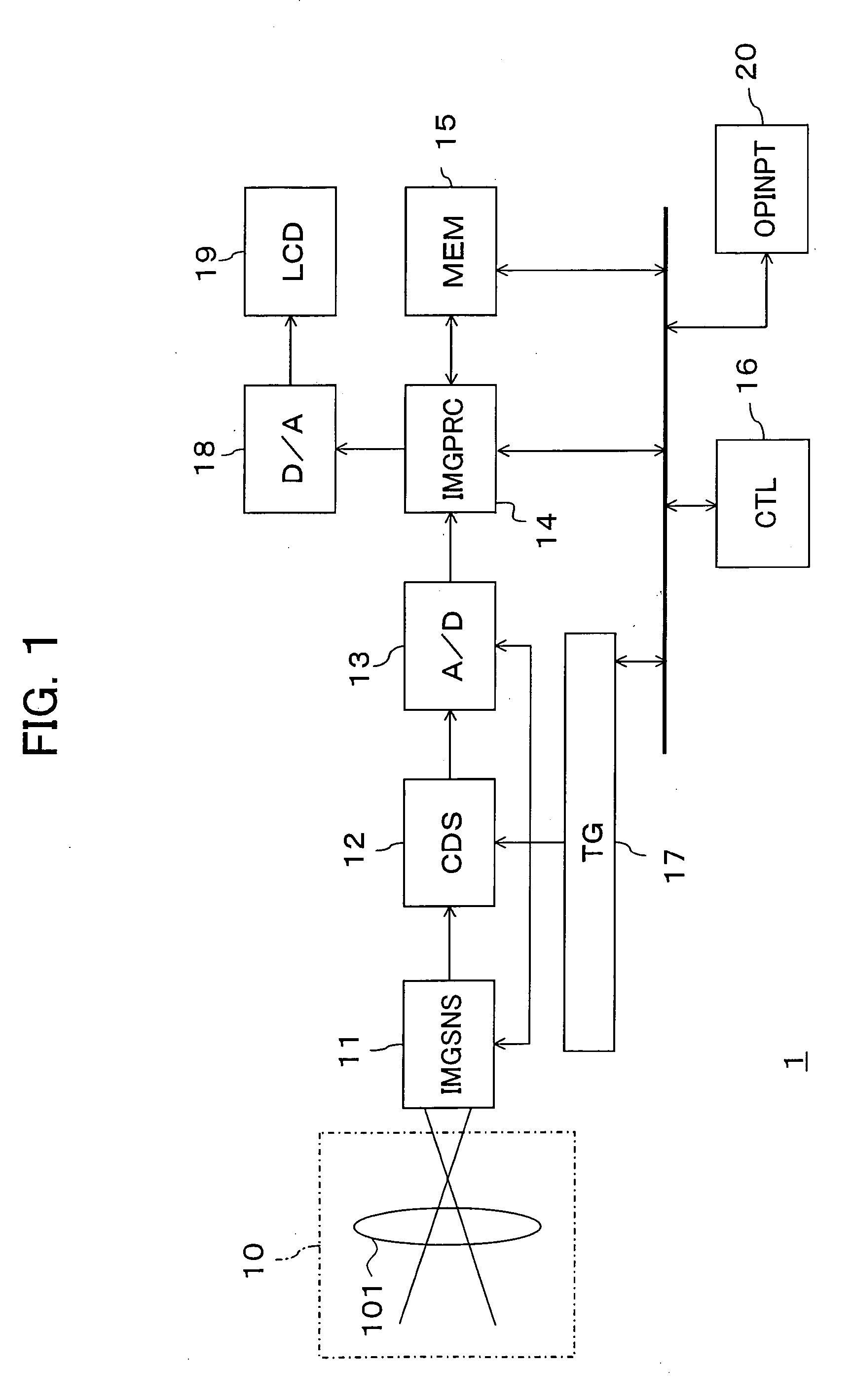
[0063]FIG. 1 is a block diagram showing a first embodiment of an imaging device according to the present embodiment. The present imaging device 1 has components classified generally as an optical system, a signal processing system, a recording system, a display system and a control system.

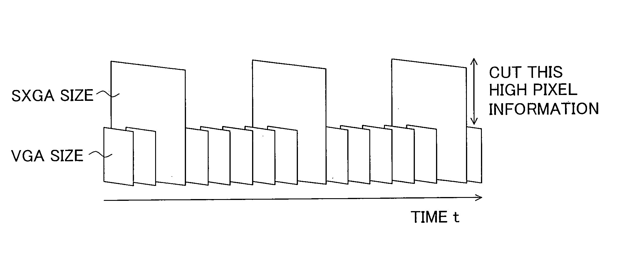
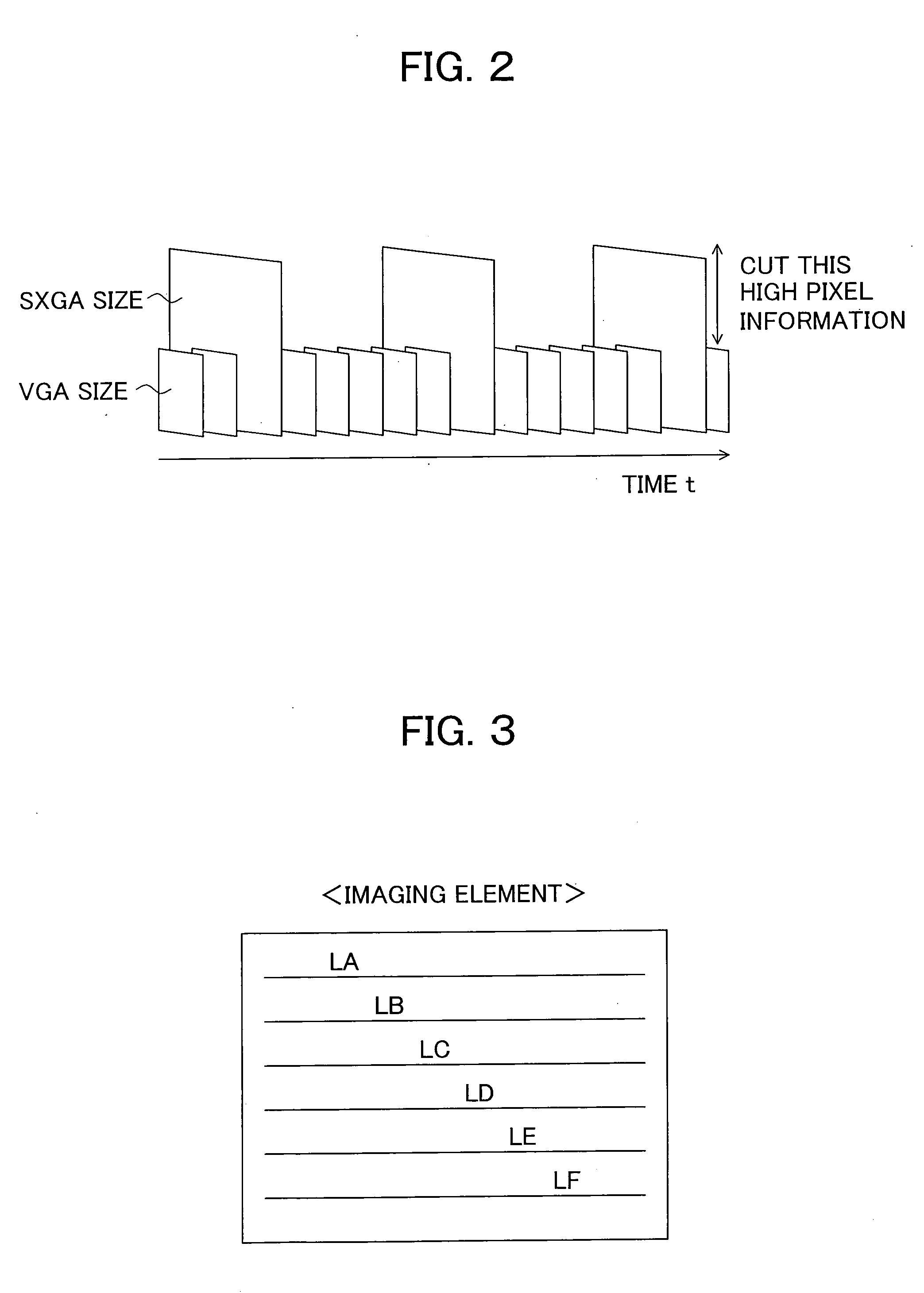
[0064] The imaging device 1 according to the present embodiment generates a first compressed image by compressing image data of high pixel with intra-frame compression in the signal processing system in capturing a moving image, generates a second compressed image by compressing image data of low pixel with inter-frame compression in a front period and / or in a rear period of the period generating the first compressed image. Further, when a screen of the second compressed image is designated, the imaging device 1 generates still image data having high-resolution showing a designated screen by decompressing and decoding by the other compressed image including the second compressed image and the firs...

second embodiment

[0165]FIG. 9 is a block diagram showing the second embodiment of a point imaging device of the present invention.

[0166] The difference point of an imaging device 1A of the second embodiment from the above-mentioned imaging device 1 of the first embodiment resides in that the imaging device 1A has a readout circuit (RO) between an image sensor 11 and a CDS 12 and adopts an image readout control method of average / summing integration of pixels.

[0167] The readout circuit 12 is controlled timing by a timing generator 17. Since the other composition is similar to the first embodiment basically, hereinafter, composition and function of the readout circuit 21 will be explained mainly.

[0168] As mentioned above, in the present second embodiment, the readout circuit 21 is arranged and an image readout control method of average / summing integration of pixels is adopted.

[0169] Generally, when it may be capture of number of pixels smaller than an imaging element, data thinned pixels or perform...

third embodiment

[0191]FIG. 12 is a block diagram showing a third embodiment of an imaging device according to the present invention. FIG. 13 is a block diagram showing an example of a configuration of a readout circuit according to the third embodiment.

[0192] The difference point of an imaging device 1B of the present third embodiment from the imaging device of the above-mentioned second embodiment resides in that the readout circuit 21A selects average (high luminance to normal luminance), addition of a first predetermined amount (somewhat low luminance), addition of a second predetermined amount (middle low luminance) and addition of a third predetermined amount (fairly low luminance) in accordance with the luminance, changes a reference voltage Vref of an A / D converter 13A in accordance with a degree of the addition and suppresses a fluctuation of the level.

[0193] Concretely, a reference voltage supply circuit (RVSP) 22 is designated so that when the selection circuit 224A selects averaging re...


PUM


Abstract

An imaging device having nonconventional and a completely new imaging method and an image generation method of the imaging device, wherein the imaging device has an image processing section generating a first compressed image compressed high image data with intra-frame compression in capturing single moving image data and a second compressed image compressed low image data with inter-frame compression in a front period and/or in a rear period of a period generating the first compressed image as one stream, where the imaging device generates still image data having high-resolution indicating one screen designated by decompression and decoding by the second compressed image and the other compressed image including the first compressed image when one screen of a second compressed image is designated.

Description

CROSS REFERENCES TO RELATED APPLICATIONS [0001] The present invention contains subject matter related to Japanese Patent Applications No. 2004-053831, 2004-053832 and 2004-053833 filed in the Japan Patent Office on Feb. 27, 2004, and Japanese Patent Applications No. 2004-218204 and 2004-218205 filed in the Japan Patent Office on Jul. 27, 2004, the entire content of which being incorporated by reference. BACKGROUND OF THE INVENTION [0002] 1. Field of the Invention [0003] The present invention relates to an imaging device such as a digital camera and an imaging method, in more detail, relates to an imaging device handling an image retrieved as a moving image mainly (comparatively small number of pixels) and an image able to be handled as a still image (comparatively large number of pixels) on a same stream and an image generation method of an imaging device. [0004] 2. Description of the Related Art [0005] There has been proposed a digital camera which compresses a digital video signal...

Claims


Application Information

Patent Timeline
IPC IPC(8): H04N3/14H04N5/225H04N5/232H04N5/235H04N5/335H04N5/76H04N5/77H04N5/91H04N5/917H04N7/26H04N7/50H04N9/04H04N9/083H04N9/79H04N9/804
CPCH04N3/1562H04N19/162H04N5/23245H04N5/2353H04N5/772H04N9/045H04N9/7921H04N9/8045H04N9/8047H04N19/159H04N19/172H04N19/46H04N19/102H04N19/61H04N5/232H04N23/667H04N23/63H04N23/73H04N25/42H04N25/445H04N25/70H04N25/134H04N23/00
Inventor YOSHIKAWA, SEIJISAWADA, RYUICHI
Owner KYOCERA CORP
Why Eureka
Try Eureka