Wireless relay system, wireless relay apparatus, and wireless relay method

a wireless relay and wireless relay technology, applied in repeater/relay circuits, transmission monitoring, instruments, etc., can solve problems such as increasing receiver noise, affecting the effect of receiver signal quality, and requiring a highly advanced technology of canceling coupling loop interference wav

Inactive Publication Date: 2005-09-01
NTT DOCOMO INC
View PDF16 Cites 86 Cited by
  • Summary
  • Abstract
  • Description
  • Claims
  • Application Information

AI Technical Summary

Benefits of technology

[0024] In the wireless relay system according to an embodiment of the present invention, in a case of relaying a signal by using an OFDM transmission method, the wireless relay apparatus may include an IFFT part for performing an IFFT process to generate the transmission signal, and an FFT part for performing an FFT process on the reception signal, and the first wireless station includes an OFDM frame generation part for inserting a null signal into a portion of a time / frequency domain and generating a frame that is to be transmitted to the wireless relay apparatus.

Problems solved by technology

That is, a characteristic degraded by generation of oscillation is a problem.
There is a problem in which a highly advanced technology of canceling the coupling loop interference wave is required for swiftly corresponding to abrupt changes of the coupling loop interference wave.
However, the coupling loop cancellation method disclosed in Japanese Laid-Open Patent Application No. 2003-174392 has a problem of increasing noise in the receiver.
Accordingly, the bit error rate tends to increase.
Furthermore, the coupling loop cancellation method disclosed in Japanese Laid-Open Patent Application No. 2001-186073 has a problem of increasing the error rate in the receiver apparatus by applying a disturbance to a signal that is to be originally transmitted.
Furthermore, in the coupling loop cancellation method disclosed in Japanese Laid-Open Patent Application No. 8-331016, since the estimated channel value relies on a frequency that is used, accuracy in estimating the channel of the coupling loop is liable to deteriorate, and preparation of a frequency band for estimating the coupling loop interference wave would be necessary.
Furthermore, in the coupling loop cancellation method disclosed in Japanese Laid-Open Patent Application No. 2000-244382, there is a problem that communication between a transmitter apparatus and a receiver apparatus is temporarily interrupted at a timing unexpected by the transmitter apparatus.

Method used


Image

  • Wireless relay system, wireless relay apparatus, and wireless relay method
  • Wireless relay system, wireless relay apparatus, and wireless relay method
  • Wireless relay system, wireless relay apparatus, and wireless relay method

Examples


first embodiment

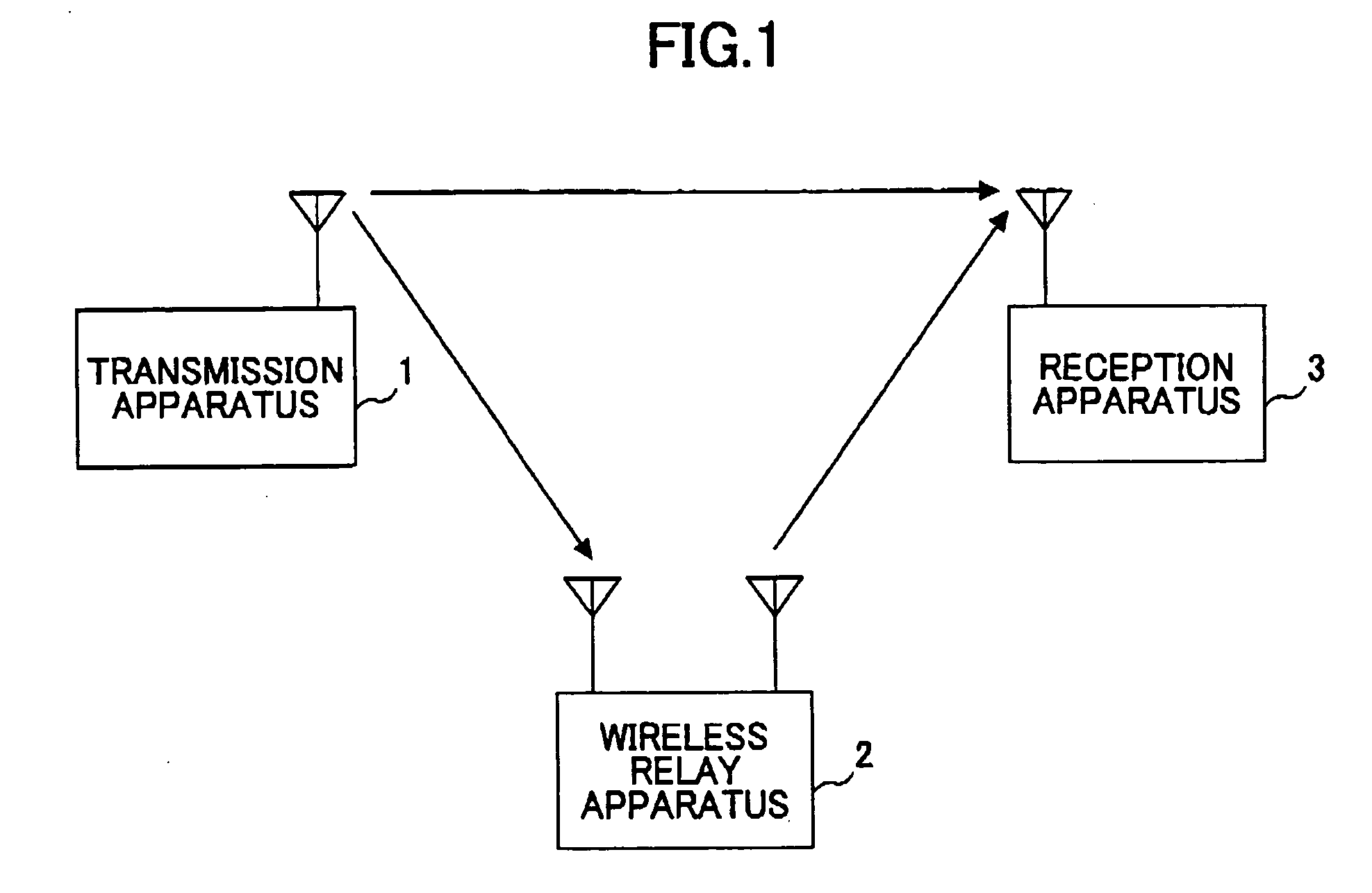
[0049] An example of a wireless relay system according to a first embodiment of the present invention is shown in FIG. 1. In FIG. 1, the wireless relay system includes a transmission apparatus 1, a wireless relay apparatus 2, and a reception apparatus 3.

[0050] The transmission apparatus 1 and the reception apparatus 3 in the first embodiment of the present invention are described below by assuming that the relation between the transmission apparatus 1 and the reception apparatus 3 is a relation of a base station (transmission apparatus 1) and a mobile station (reception apparatus 3).

[0051] The signals received by the reception apparatus 3 include a signal directly received from the transmission apparatus 1 and a signal received via the wireless relay apparatus 2. A signal transmitted from the transmission apparatus 1 is first received in the wireless relay apparatus 2, and is retransmitted to the reception apparatus 3 at the same frequency. Furthermore, the wireless relay system o...

second embodiment

[0071] In a system executing OFDM communication, all transmission signals in a predetermined time do not need to be inserted with null signals, but alternatively, a symbol(s), which only forms a part of a sub-carrier, may be made into a null signal(s).

[0072]FIG. 5 is a drawing showing an exemplary configuration of a wireless relay apparatus according to a second embodiment of the present invention. FIG. 6 is a drawing showing an exemplary configuration of a transmission frame generated by a transmission frame generation part of a transmission apparatus according to the second embodiment of the present invention.

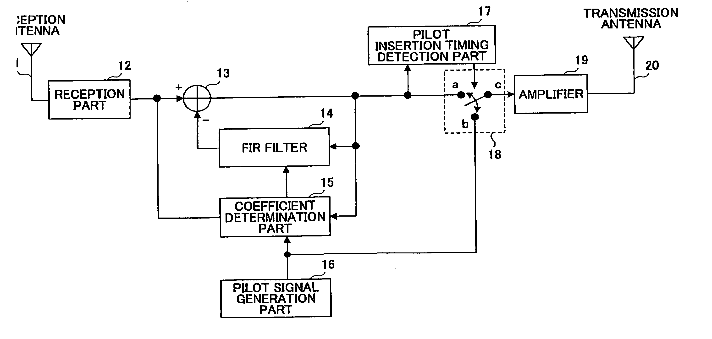
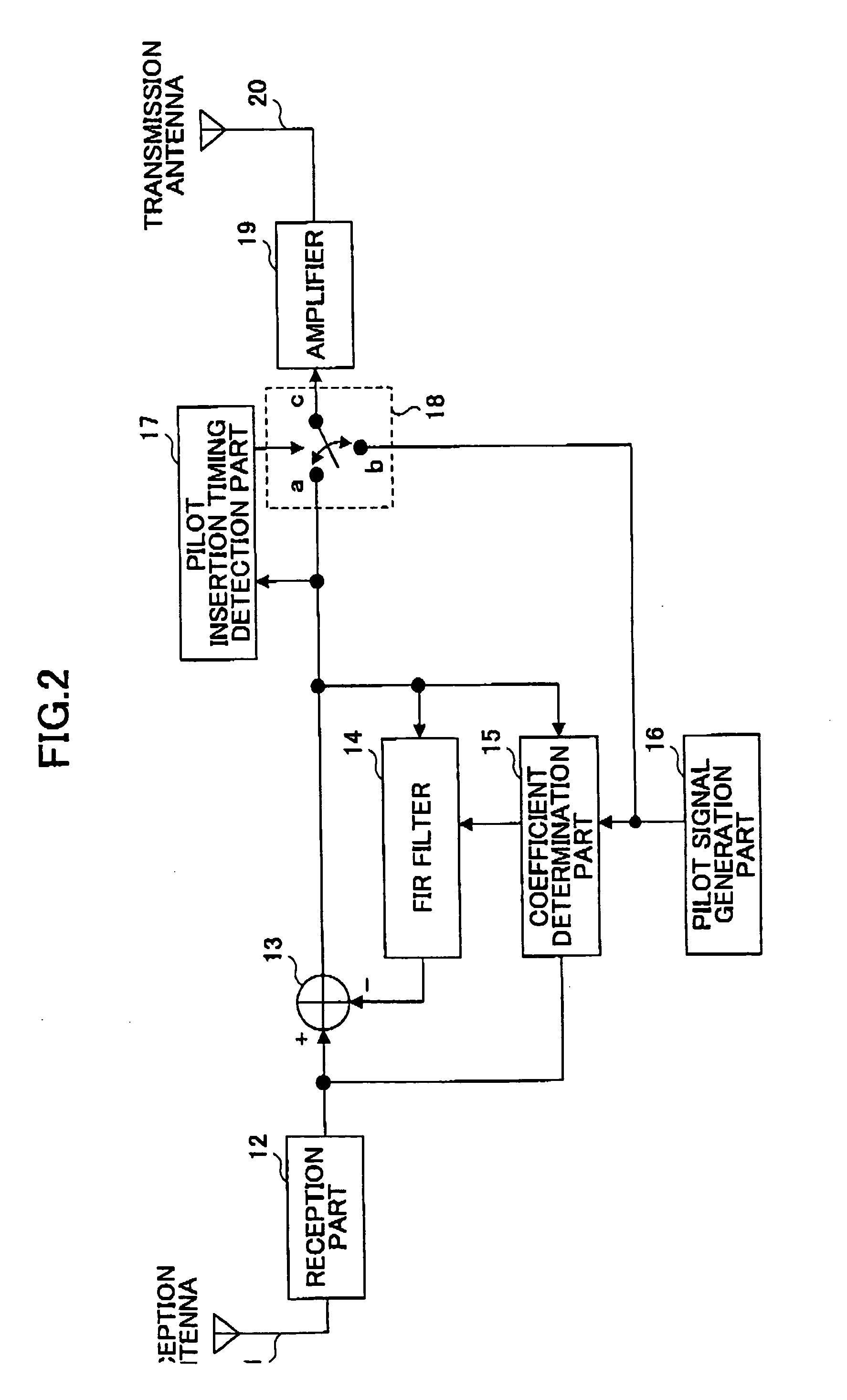
[0073] The wireless relay apparatus shown in FIG. 5 has a configuration similar to that of the wireless relay apparatus 2 according to the first embodiment of the present invention shown in FIG. 2, but is also provided with an FFT part 51 for performing an FFT process on a reception signal(s), and an IFFT part 59 for performing an IFFT process on a transmission signal(s). T...

third embodiment

[0079] Although the second embodiment of the present invention is described supposing the same power amplification factor is allocated against all subcarriers, in a case where OFDM transmission is employed, a wireless relay apparatus according to a third embodiment of the present invention changes the electric power amplification factor of each sub-carrier for attaining a more satisfactory communications quality. That is, the wireless relay apparatus according to the third embodiment of the present invention has a function of controlling the electric power amplification factor of each sub-carrier.

[0080] As shown in FIG. 7, the wireless relay apparatus according to the third embodiment of the present invention has a configuration similar to that of the wireless relay apparatus 2 according to the second embodiment of the present invention shown in FIG. 5, but is also provided with a transmission apparatus insertion pilot signal generation part 62 which generates the same pilot signal...


PUM


Abstract

A wireless relay system for relaying a radio signal transmitted from a first wireless station to a second wireless station via a wireless relay apparatus is disclosed. The wireless relay system includes a relay control part for receiving transmission symbols transmitted from the first wireless station and refraining from relaying a portion of the symbols, a pilot signal transmission part for transmitting a pilot signal that is inserted into a section of the portion of the transmission symbols, a coupling loop interference wave estimation part for receiving the pilot signal and estimating a coupling loop interference wave based on the pilot signal, and a coupling loop interference wave cancellation part for subtracting the estimated coupling loop interference wave from a reception signal.

Description

BACKGROUND OF THE INVENTION [0001] 1. Field of the Invention [0002] The present invention generally relates to a wireless relay system, a wireless relay apparatus, and a wireless relay method for wireless communication between a transmission apparatus and a reception apparatus via a single or a plurality of wireless relay apparatuses. [0003] 2. Description of the Related Art [0004] Recently and continuing, a method of executing relay between a transmission apparatus and a reception apparatus by using the same frequency band with a wireless relay apparatus (=relay device) is being considered. In employing the wireless relay apparatus, it is important to control oscillation created by a coupling loop interference wave from a transmitter antenna to a receiver antenna. That is, a characteristic degraded by generation of oscillation is a problem. [0005] Furthermore, since the relay is considered as a method that is mainly employed for broadcasting, controlling the coupling loop interfere...

Claims


Application Information

Patent Timeline
Patent Type & Authority Applications(United States)
IPC IPC(8): H04J11/00H04B7/015H04B7/15H04B7/155H04B7/26H04J99/00
CPCH04B7/15585H04L5/0023H04L27/2602H04L5/0048H04L25/0226H04L5/0032G07F17/32A63F13/90A63F2250/14
Inventor FUJII, HIROMASASUDA, HIROHITOTANAKA, TETSU
Owner NTT DOCOMO INC
Why Eureka
Try Eureka