Mixer apparatus and sound signal processing method

a technology of mixing apparatus and sound signal, which is applied in the direction of transducer casing/cabinet/support, electrical transducer, instruments, etc., can solve the problem of difficulty in cascading different models

Inactive Publication Date: 2005-09-01
INTEL CORP +1
View PDF6 Cites 17 Cited by
  • Summary
  • Abstract
  • Description
  • Claims
  • Application Information

AI Technical Summary

Benefits of technology

[0004] In view of the foregoing, it is an object of the present invention to provide a mixer apparatus, sound signal processing method and program which can achieve flexible input / output of cascade-related signals using a plurality of different types of terminals.
[0005] It is another object of the present invention to provide a mixer apparatus, sound signal processing display method and program which can achieve flexible connection between models differing from each other in cascade input / output specifications, and which allow a user to readily grasp a state of the cascade connection.
[0006] It is still another object of the present invention to provide a mixer apparatus, sound signal processing method and program which can achieve flexible cascade connection between models differing from each other in cascade input / output specifications.
[0007] According to a first aspect of the present invention, there is provided an improved mixer apparatus, which comprises: first input terminals that input first sound signals of a plurality of channels; a plurality of mixing buses that perform mixing processing on sound signals; a second input terminal that inputs second sound signals of a plurality of channels, the channels of the second sound signals corresponding to the plurality of mixing buses; an input processing section that performs equalizing processing on sound signals supplied to the first input terminals, and sends the sound signals, having been subjected to the equalizing processing, to one or more desired mixing buses among the plurality of mixing buses; and a control section that performs control such that: the input processing section is supplied with the second sound signals instead of a group of sound signals that constitute at least a portion of the first sound signals; and signal processing, including the equalizing processing, is performed by the input processing section on the supplied second sound signals so that the second signals having been subjected to the equalizing processing are sent to one or more desired mixing buses among the plurality of mixing buses. With such arrangements, the mixer apparatus of the invention can achieve flexible input of cascade-related signals using a plurality of different types of terminals. The control by the control section is permitted when the mixer apparatus is set in a predetermined operation mode. In this manner, the mixer apparatus is allowed to operate in an optimal operation mode in accordance with a model of another mixer to which the mixer apparatus is cascaded.
[0008] According to a second aspect of the present invention, there is provided an improved mixer apparatus, which comprises: first output terminals that output first sound signals of a plurality of channels; a plurality of mixing buses that perform mixing processing on sound signals; a second output terminal that outputs second sound signals of a plurality of channels, the channels of the second sound signals corresponding to the plurality of mixing buses; an output processing section that performs equalizing processing on a sound signal outputted from each of the mixing buses and sends the sound signals, having been subjected to the equalizing processing, to the first output terminals as the first signals; and a control section that performs control such that sound signals having not been subjected to the equalizing processing, outputted from individual ones of the mixing buses, are outputted, via the first output terminals, instead of a group of sound signals that constitute at least a portion of the first sound signals of the plurality of channels outputted by the output processing section. With such arrangements, the mixer apparatus of the invention can achieve flexible output of cascade-related signals using a plurality of different types of terminals. The control by the control section is permitted when the mixer apparatus is set in a predetermined operation mode. In this manner, the mixer apparatus is allowed to operate in an optimal operation mode in accordance with a model of another mixer to which the mixer apparatus is cascaded.
[0010] According to a fourth aspect of the present invention, the mixer apparatus of the above-mentioned second aspect further comprises a display section that, when sound signals, having not been subjected to the equalizing processing, are outputted via the first output terminals under control of the control section, displays a setup screen indicating the output, via the first output terminals, of the sound signals. Thus, the present invention permits flexible cascade connection between models differing in the cascade input / output specification, and also allows the user to readily grasp or ascertain a cascade connection state by viewing the setup screen.

Problems solved by technology

However, where there is employed a digital mixer of a given model (“first model”) using, as its terminals for normal input and output channels, terminals of the same type as cascade connecting terminals of another digital mixer of another model (“second model”), then all sound signals output from the first model to the second model can be handled in the second model only as “cascade signals”, which was very inconvenient.
Further, because the specifications of the cascade connection variously differ among various models, it was very difficult to cascaded different models.

Method used


Image

  • Mixer apparatus and sound signal processing method
  • Mixer apparatus and sound signal processing method
  • Mixer apparatus and sound signal processing method

Examples


Embodiment Construction

1. Example Hardware Setup of Embodiment:

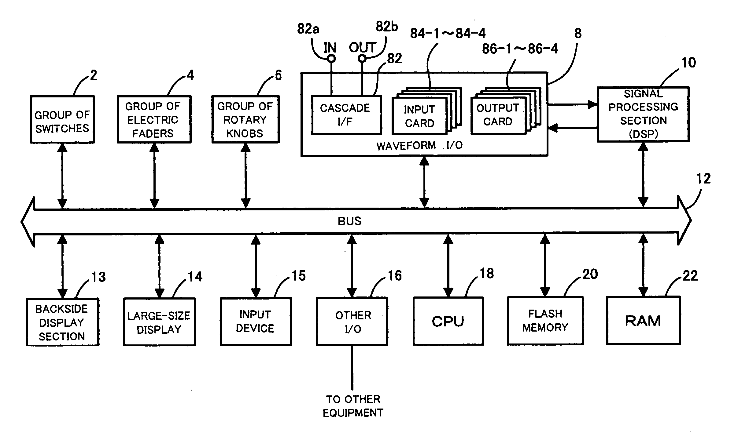
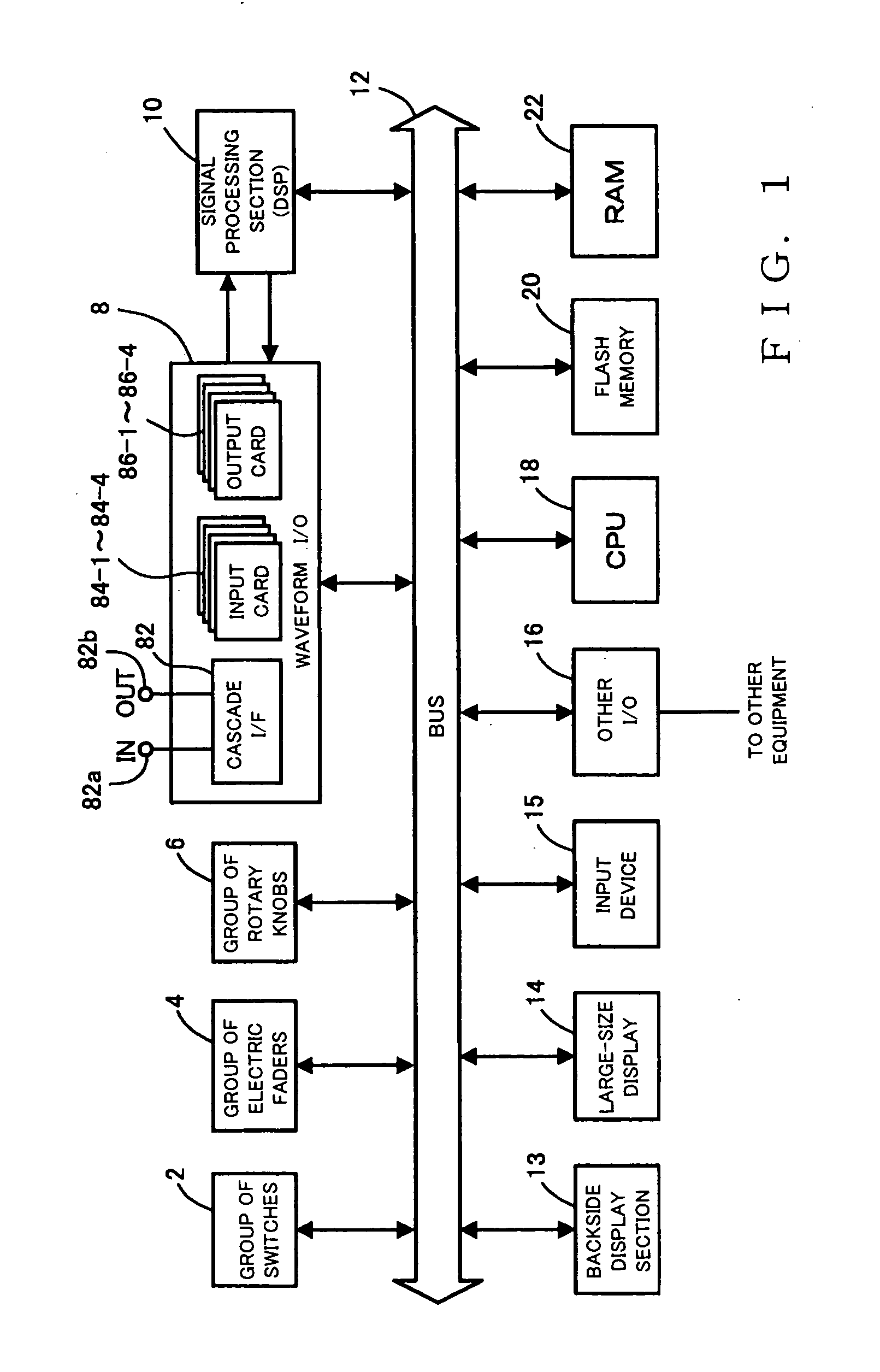
[0034] A description will be made about an example general hardware setup of a digital mixer in accordance with an embodiment of the present invention, with reference to FIG. 1.

[0035] As shown, the digital mixer of the present invention includes a group of electric faders 4 that are provided to adjust signals levels of individual input and output channels on the basis of operation by a user or human operator. The group of electric faders 4 are also constructed so that an operating position of any of the electric faders 4 is automatically set in response to an operation command supplied via a bus 12.

[0036] Reference numeral 2 represents a group of switches that includes various switches and LED keys, and the illuminating / deilluminating (OF / OFF) state of an LED built in each of the LED keys is set via the bus 12. Group of rotary knobs 6 includes a plurality of rotary knobs for setting left and right sound volume balance of each input / output ...


PUM


Abstract

Once a mixer is set in a predetermined operation, an input-logical-channel selecting section supplies sound signals, input via a cascade input terminal, to an input signal processing section via an input patch section, so that the sound signals can be mixing-processed as sound signals of normal input channels. At the same time, a portion of sound signals input via an input terminal are supplied to mixing buses, so that these sound signals can be handled as cascade-related signals. In accordance with a model of another, or cascaded-to, mixer, arrangements are made such that normal-input / output-channel input terminals can be assigned to cascade input / output purposes. With a block diagram display section indicating what signals the individual input / output terminals are currently assigned to within the mixer, a user can grasp at a glance the current assignment state.

Description

BACKGROUND OF THE INVENTION [0001] The present invention relates to a mixer apparatus and a sound signal processing method suited for use in a digital mixer, and a program therefor. [0002] Generally, in digital mixers, equalize processing, sound volume adjusting processing, etc. are performed individually on sound signals of a plurality of input channels, and then the thus-processed sound signals are supplied to a plurality of mixing buses where these sound signals are mixed together. Because the number of the input channels processable by one digital mixer is limited, there has been known and used the so-called “cascade connection” technique. Such cascade connection is intended to couple or input the output signals (“cascade signals”) of the individual mixing buses of one digital mixer directly to the mixing buses of another digital mixer, so as to allow the two digital mixers to function as if they were one large-scale mixer having input channels equal in number to the total numbe...

Claims


Application Information

Patent Timeline
Patent Type & Authority Applications(United States)
IPC IPC(8): H04H60/04
CPCH04H60/04
Inventor HAMADA, ATSUOTERADA, KOTARO
Owner INTEL CORP
Why Eureka
Try Eureka